Table of Contents

Spectroscopy Module
Model No. D2-210
Document Revision: 1
Document Last Updated on 2024/03/27 15:58
Please read Limited Warranty and General Warnings and Cautions prior to operating the D2-210. D2-210 website and data sheet.
Description
The D2-210 saturated absorption spectroscopy module provides error signals derived from saturated absorption spectroscopy of atomic rubidium, cesium, or potassium. It contains a vapor cell, internal temperature controller, balanced photodetectors, and optics. Temperature control stabilizes the number density of atoms in the cell, and a balanced photodetection circuit compensates for intensity drifts giving stable control over the lock point for side locking applications. The photodiode output is shot-noise limited out to greater than 5 MHz for photocurrents of 50 μA and above. The high bandwidth of the feedback enables tight solid locking that is immune to vibrations and shock. The D2-210 is powered by a cable that plugs into the power connectors on any D2 series electronics module.
The D2-210 is a significant upgrade to the D2-110 incorporating many suggestions from our customers:
- The module is magnetically shielded to allow close placement to the D2-100 DBR laser module.
- An adjustable λ/2 waveplate enables the user to control light level pickoff over a wide range of input power levels.
- In addition to rubidium and cesium, the D2-210 can now be configured with potassium.
- Ordering options exist for Doppler subtraction and fiber coupling.
- Future ordering options will include lock signals derived by DAVLL and Zeeman Modulation spectroscopy.
Purchase Includes
- D2-210 Spectroscopy Module
- VPN00463 SMA cable (6ft)
- VPN00410 Hirose-to-D Sub 9-pin (shipped under separate line item; specify for use with D2)
- VPN00475 Hirose-to-Hirose power cord (shipped under separate line item; specify for use with ICE)
- VPN00367 Adjustment tool
Absolute Maximum Ratings
Note: All modules designed to be operated in laboratory environment
Specifications
Powering the D2-210
The D2-210 requires +5 and ±15 VDC and ground to operate. The power input is via a female 6-pin Hirose connector HR10A-7TR-6SA(73). Depending on your order configuration, you should have received a power cable with this connector on one end and either the same on the other end (typically for use with ICE products) or a DB-9 connector (for use with D2-products).
If you are using the DB9-to-Hirose cable, but not a Vescent D2-005 power supply, table 3 below details which pins on the Hirose require which voltages.
Theory of Operation


Input light passes through an adjustable λ/2 waveplate and polarizing beamsplitter (PBS) that directs a user-controlled portion of the beam to the vapor cells and detectors. (For the fiber-coupled option the user will generally input most of the light.) The beam is then passed through a cleanup PBS and split on a 50:50 non-polarizing beamsplitter (NPBS). One portion is then passed through a reference vapor cell (Doppler subtraction option) or passed directly to the reference photodiode.
The remaining portion is passed through a fixed λ/2 waveplate and PBS to split off the pump beam from the probe beam. The pump beam is directed to the Output Optics assembly where it is combined with the probe beam on a PBS in a counter-propagating configuration. The pump beam is dumped through the reflection port of the PBS that separated the pump and probe and terminates on the wall of the housing. The probe is detected on the signal photodiode.
The beam diameters were designed to provide enough photocurrent (~50-100 μA) to give shot-noise-limited performance out to 5 MHz while limiting saturation broadening. For Vescent's DBR lasers, the bandwidth is useful to provide for tight and stable locking by feedback to injection current.
Inputs, Outputs, and Controls
Input Connector (6-pin circular)
Never connect this device to its power supply when the power supply is switched on and supplying power. Always turn off the power supply, make connections to the device, and then re-energize the power supply.
Power and temperature control signals from the D2-series power bus, the ICE-PB1, or other power supply are made through a 6-pin circular connector (HR10A-7TR-6SA(73)). The pin definitions (pin numbers are marked on the connectors) are listed below. figure 3 below may be useful.
 Fig. 3: Pin numbering on female Hirose 6-pin connector
| Hirose Pin (VPN00410 and VPN00475) | DB-9 Pin (VPN00410) | Input Voltage | Max Current Draw | Notes |
|---|---|---|---|---|
| 1 | 4 and 5 | Signal Power Ground | Return path for power rail. | |
| 2 | 8 | -7 V to -15 V | 100mA | See note below. |
| 3 | 9 | +7 V to +15 V | 100 mA | See note below. |
| 4 | 6 and 7 | +5 V | 1.5 A / 2.5 A | 2.5 A max with Doppler subtraction option, 1.5 A max without. |
| 5 | No Connect | |||
| 6 | 1 and 2 | +5 V Ground | Return path for high current +5V. |
Signal Output (SMA)
The photodiode signal is output through an SMA connector. Connect to ERROR INPUT on the Laser Servo.
Balance Adj.
Sets the fraction of the Reference photocurrent to be subtracted from Signal. Setting the lockpoint close to zero Volts will give the best subtraction of relative intensity noise (RIN) on the incoming laser.
Temperature Adj.
10-turn trim pot that sets temperature from 25°C (fully CCW) to 65°C (10 turns CW). The 5-turn point is approximately 42°C. Note that the vapor cells are heated only, so setting the temperature below room temperature essentially disables temperature control. The following table gives approximate temperature settings for the three available alkali options:
Temperature Loop Gain Adj.
In newer units, there is a middle trimpot for adjusting the gain on the PID temperature loops. Higher gain (clockwise) will result in faster temperature settling until oscillation occurs.
Temperature Bias Adj.
[Note: this adjustment is only available on older D2-210 models.] For the Doppler subtraction option this control enables the user to input a small temperature difference between the reference and signal vapor cells. In the fully CCW position the signal vapor cell heater gets all the current. In the full CW position the reference cell heater gets twice the current as the signal cell. This adjustment can be used to place the optimum point for Doppler Subtraction closer to zero Volts.
This adjustment only has an effect with the -DS, Doppler Subtraction option.
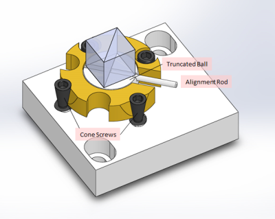
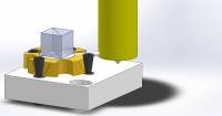
Tilt Plate
A polarizing beamsplitter (PBS) is fixed to a ball joint formed by a truncated steel ball held by a conformal brass ring. Two cone screws clamp the ring against the ball and fix the position of the PBS. See Alignment Procedure below for instructions on how to align and fix the PBS.
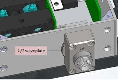
λ/2 Waveplate
A waveplate attached to the front plate by magnets can be used to select the splitting fraction of the Tilt Plate PBS.
Quick Setup Guide
- Set the D2-210 in the beam path of the laser so that the beam goes through the center of the input and output holes. Loosely apply the four 1/4-20 mounting screws and washers to affix the unit to the laser table.
- Using the cable provided, connect the 8-pin circular Hirose connector to the D2-210 and connect the D-sub 9-pin connector to a free power connector on the D2-005 or other Vescent electronics module. If you are using an alternate power supply, refer to the table above for correct voltage input connections.
- Connect the SMA connector to an oscilloscope.
- If you have the fiber-coupling option, connect a polarization maintaining fiber with FC/APC connector to the input fiber connector. At least 1 mW of optical power should exit the fiber. Skip to step 9.
Note: When coupling the laser into the fiber, strive to properly align the laser polarization to the polarization axis of the PM fiber. Otherwise you will observe significant temperature and stress induced birefringence leading to input power fluctuations.
- Open the top cover.
- Block the reference photodiode with a strip of index card.
- Adjust the light level by rotating the λ/2 waveplate to obtain about -1 V of signal.
- Shift the D2-210 about the mounting screws to maximize the light level.
- Set the laser to scan over the alkali transitions. If you observe spectroscopy, try to move the D2-210 to optimize the spectrum.
- Tighten the 4 mounting screws.
- In about 20 min, a green LED should light (visible through the port next to SMA connector) indicating the final temperature has been achieved.
- If the spectroscopy does not look similar to the plots shipped with the device, proceed to the Alignment Procedure below.
- Use the Balance Adjust control to set the lock point to ground.
Aligning the Spectroscopy Module
The spectroscopy module is shipped factory aligned and should not require alignment if ordered with a matching D2-100-DBR laser or if ordered with the fiber input (-FC) option. If the unit was not aligned to a laser at the factory, or if it falls out of alignment, the following steps can be used:
- Fashion several 1 cm x 3 cm cards from an index card for use as viewing screens.
- Remove the cover on the Spectroscopy Module.
- If working with a Vescent D2-100 laser, follow the instructions in the DBR Laser Module section to adjust laser steering so the beam passes through the center of the input and output apertures on the laser module.
- Adjust the λ/2 waveplate on the input face to maximize the light power reflected by the input PBS.
- If required, loosen the two 2-56 screws holding the tilt-plate assembly into the spectroscopy module and slide the assembly so that the input beam is centered on the PBS.
- Loosen the two cone screws using a 0.050“ Allen wrench. Then tighten the cone screw farthest from the alignment rod until the brass ring just begins to grab. Tighten the second cone screw similarly. The goal is when moving the PBS with the alignment rod, it moves easily, but with some resistance.
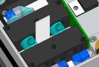
- Place the alignment tool so that the indent captures the end of the alignment rod as shown below.
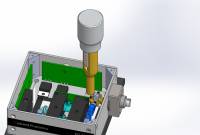

- To use the adjuster, gently push down to seat the point as shown above. To adjust the beam right and left, use a small twisting motion. To adjust the beam up and down, use your other hand to turn the knurled cylinder.
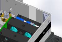
- Place a viewing card in the path of the pump beam as shown. Center the beam through the passage.
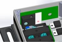
- Move the viewing card to the output port of the pump/probe PBS as shown below. Adjust the beam so that it is centered on the output face of the PBS. At this point, the beams should be well aligned and overlapped.
- Place a viewing card in front of the Reference photodiode as shown below.
- Adjust the λ/2 waveplate to give approximately 1 Volt at the output SMA (with Reference beam blocked).
- Scan the laser until the Doppler broadened transitions are visible. Doppler-free hyperfine transitions should be clearly evident. For 87Rb, the cycling transition should have a depth between 20 and 50 mV. At this stage, the input PBS can be adjusted to improve the Doppler-free transitions; however, these adjustments are admittedly challenging. Generally it's best to repeat the above procedure and make sure the saturation beam dump is well centered on the output PBS and then check the quality of the spectroscopy. The 2-56 screws holding the input and output optics assemblies can also be loosened to shift the optics assemblies around to improve the spectroscopy.
- Tighten the cone screw farthest from the alignment rod. Then tighten the last cone screw. The order helps. If the spectroscopy changes then repeat the above alignment steps, but with the cones screws just a bit tighter.
- Unblock the Reference beam and use the Balance Adjust trimpot to set the desired lockpoint to ground.
- Replace the cover
The following images are representative of spectroscopy for 87Rb with (figure 8) and without Doppler subtraction (figure 7). Note that Doppler subtraction has a minimal effect on peak lock signal generated by dithering the laser (green traces).
Fig. 3: Pin numbering on female Hirose 6-pin connector
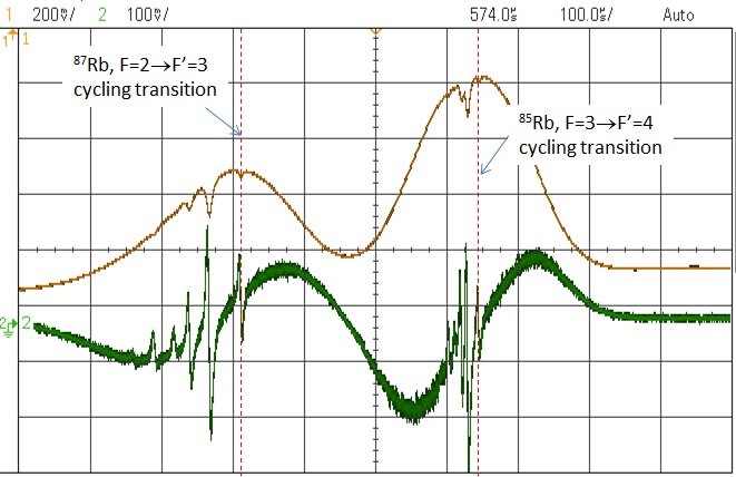 Fig. 7: Non-Doppler subtracted side- and peak-lock spectra
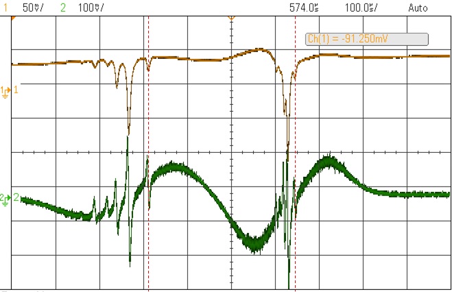 Fig. 8: Doppler subtracted side- and peak-lock spectra