
Table of Contents
Current Controller and Offset Phase Lock Servo Board
Model No. ICE-CP1
Document Revision: 1.0
Document Last Updated on 2021/08/26 14:26
Please read Limited Warranty and General Warnings and Cautions prior to operating the ICE-CP1.
The guide to programming the ICE-CP1 through serial commands can be found here. The ICE-CP1 web page can be found here.
Description
The Current Controller & Offset Phase Lock Servo Board has either a 200 mA (ICE-CP1-200) or 500 mA (ICE-CP1-500) precision current source based on the Libbrecht-Hall1) circuit and an integrated offset phase-lock laser servo. The ICE-CP1 contains a tunable PID loop filter for a robust phase-lock.
Absolute Maximum Ratings
Note: All modules designed to be operated in laboratory environment
| Parameter | Rating |
|---|---|
| Environmental Temperature | >15°C and <30°C |
| Environmental Humidity | <60% |
| Environmental Dew Points | <15°C |
Specifications
| ICE-CP1-200 | ICE-CP1-500 | Units | |
|---|---|---|---|
| Current Source | |||
| Current range | 0-200 | 0-500 | mA |
| Current setpoint resolution | 200 | 500 | μA |
| Current noise density | <100 | <200 | pA /√Hz |
| RMS Noise (10Hz - 100kHz) | <50 | <100 | nA |
| RMS Noise (10Hz - 1MHz) | <100 | <150 | nA |
| RMS Noise (10Hz - 10MHz) | <300 | <500 | nA |
| Absolute accuracy | 2 | % | |
| Offset Phase Lock Servo Input Signal | |||
| Min Offset Frequency | 250 | MHz | |
| Max Offset Frequency | Min: 9.5, Typical: 102) | GHz | |
| Max Electronic Beat-Note Input (ICE-CP1-SMA) | 10 | dBm | |
| Min Electronic Beat-Note Input (ICE-CP1-SMA) | -10 | dBm | |
| Min Electronic Beat-Note S/N (ICE-CP1-SMA) | >50 | dB | |
| Max Optical Beat-Note Input (ICE-CP1-FC) | 1 | mW | |
| Min Optical Beat-Note Input (ICE-CP1-FC)3) | 50 | μW | |
| Front-panel Input Connection (ICE-CP1-FC)4) | SC | ||
| Front-panel Input Connection (ICE-CP1-SMA) | SMA | ||
| Offset Phase Lock Servo Performance | |||
| Bandwidth5) | 1.5 | MHz | |
| Interval reference frequency drift | +/-20 | ppm | |
| PFD Noise6) | -213 | dBc/Hz | |
| Loop Filter Parameters | |||
| Proportional Gain | -72 – 0 | dB | |
| Proportional Gain Resolution | 2 | dB | |
| Integrator | 3, 10, 30, 100, 300 | kHz | |
| Differential | Off, 10, 30, 100, 300 | kHz | |
| Differential Gain | 18 | dB | |
Setting the Offset Frequency
Two numbers control the offset frequency of the ICE-CP1: The divider setting N and the reference frequency. The divider setting N can be set to N=8,16,32 or 64. The reference frequency can be generated internally with a range from 50 - 240 MHz. Or an external frequency reference can be provided (external frequency must be from 32 MHz - 240 MHz). The offset frequency of the laser is given by the following formula:
Offset = N * Reference Frequency
The table below shows the offset range for different values of N and using the internal or external frequency reference.
Understanding Gain in the OPLS
The charge pump (CP) output is proportional to phase-error when phase-locked, but the slope is proportional to the value of N. This means that when N is increased, the same voltage on the CP monitor reflects twice as much phase-error. The result is that the input to the loop filter has half as much gain with N=16 than with N=8. To compensate, the OPLS internally increases the gain of the Loop Filter by a factor of N so the user does not see a change in the closed-loop gain when changing the value of N.
Understanding the Transfer Function
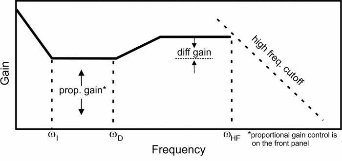 Fig. 1: Schematic of the OPLS right-side panel, showing the configurable transfer function and its user-controls.
The charge pump in the OPLS outputs a signal proportional to the phase-error and the transfer function is as shown in figure 1. However, the OPLS will typically be used to control a frequency-tunable device (such as a laser). In this configuration, the effective loop filter is not the one shown in figure 1, but includes a extra integration corresponding to converting the phase-error input to a frequency error. Thus, ωI sets the frequency transition from single-integration to double-integration and ωI from single-integration to proportional feedback. It is important to understand this 'hidden' integrator when configuring the loop filter parameters.
Calculating Phase Noise
The phase-noise specified in Section 1.3 is referenced to the phase frequency detector (PFD) at 1 Hz. To convert that to the noise measured on the actual beat-note, it must be rescaled with the following formula:
D2-135 Phase-Noise Floor = -213 + 20Log(N) + 10Log(ƒREF)
where N is the value of the divider and ƒREF is the reference frequency as measured in Hz. For more details, please see this application note.
I/O (ICE-BOX)
Only when purchased with the ICE-Box.
Beat Note Monitor
The Front Panel for the ICE-CP1 has four SMA or FC connectors. The top-most connector is an SMA which is the digitized (i.e. square-wave) version of the input beat-note after a divide-by-2. For example, if the input beat note is 6 GHz, the monitor will have a 3 GHz output. The signal is ~0 dBm in power regardless of the strength of the input beat-note signal.
External Reference Frequency Input
The Front Panel for the ICE-CP1 has four SMA or FC connectors. The second top-most connector is an SMA input for the external frequency reference. The input is AC coupled and 50 Ω terminated. Max power is 10 dBm.
Beat Note Input
The Front Panel for the ICE-CP1 has four SMA or FC connectors. The SMA connector 2nd from the bottom is the beat note signal input. When FC, this input should be a <1 mW signal containing overlapped light from both lasers. When an SMA, this input should be an electrical signal, typically the output of the D2-160 or D2-260 Beat Note Detector.
Laser Current
The Front Panel for the ICE-CP1 has four SMA or FC connectors. The bottom SMA goes to the laser and drives positive current to the laser. The center conductor of the SMA goes to the laser anode.
I/O (OEM Only)
Only for OEM versions of the ICE-CP1 purchased without the ICE-Box.
 Fig. 2: Connector and component positions on PCB.
Beat Note Input
The ICE-CP1 has one SMA connector which is the beat note signal input. This signal should be an electrical beat -note between -10dBm and 10dBm of electrical power. Input is 50 Ω terminiated.
External Reference Frequency Input
The ICE-CP1 has three UMCC (Molex PN: 0734120110) connectors. The one labelled “Ext Ref” is an UMCC input for the external frequency reference. The input is AC coupled and 50 Ω terminated. Max power is 10 dBm.
Beat Note Monitor
The ICE-CP1 has three UMCC connectors. The one labelled “BN Mon” is an UMCC containing is the digitized (i.e. square-wave) version of the input beat-note after a divide-by-2. For example, if the input beat note is 6 GHz, the monitor will have a 3 GHz output. The signal is ~0 dBm in power regardless of the strength of the input beat-note signal.
Laser Current
The ICE-CP1 has three UMCC connectors. The one labelled “Laser” goes the laser and drives positive current to the laser. The center conductor of the UMCC goes to the laser anode.
Quick Start Commands Guide (Laser Current)
Please see the Quick Start Commands Guide (Laser Current) in the ICE-CS1 manual.
Quick Start Commands Guide (Offset Phase Lock Servo)
Please see Overview of Commands and Basic Usage, Common Commands to all Slave Boards and Current Controller & Offset Phase Lock Servo Commands for a complete command list. Set the ICE-MC1 to communicate with the slot that this ICE-CS1 is in (see Master and Control Board Overview for details).
This content is not yet available, sorry.