This is an old revision of the document!
Table of Contents
SVS Fiber Frequency Comb Module Quick Start Guide
Document Last Updated on 2021/12/07 18:43
Please read Limited Warranty and General Warnings and Cautions prior to operating the FFC-100.
Useful Links
Vescent manuals page.
FFC-100 API.
FFC-100 web page.
Github page for FFC-100 firmware revisions
FFC-100 Manual
Please check back for added functionality. Contact sales [at] vescent [dot] com for questions and corrections, or to request added functionality.
Notice
 | Do not block the airflow vents on the side of the chassis or the fan inputs & outputs on either the FFC-100 or the SLICE-FPGA. |
| The mode-lock indicator on the GUI front panel cannot detect CW breakthrough. Keep the oscillator current within the range specified in your product's final test documentation or CoC. |
Proper Usage
 | If this instrument is used in a manner not specified by the manufacturer in this manual or other relevant literature, protection provided by the instrument may be impaired. |
| Successful implementation of the SVS FFC Module depends critically on the design of the whole system: SVS FFC Module, phase locking electronics, and any references to which the SVS FFC Module is locked or vice versa. |
Purchase Includes
- SVS Fiber Frequency Comb Module
- Power cord for your country (if known)
- Instructions on how to download & install control software
- Final Test Documentation
- Other items depending on specific configuration
Absolute Maximum Ratings and Power Input
Note: All modules designed to be operated in a laboratory environment.
Operating the SVS FFC Module
This document provides basic instructions on how to operate the Vescent Photonics SVS Fiber Frequency Comb Module in conjunction with the Vescent SLICE-FPGA. It is important to note that the SVS FFC Module itself does not come with a built in GUI, and as such communication must be done through the Serial Command API or the FPGA Software. This document will walk through usage of the Serial Command interface including several basic commands, as well as using the FPGA Software to obtain and optimize your lock.
System Set-up
Initial Connections
To begin, connect the SVS FFC Module to power, turn it on, then connect it to a Windows 10 computer using the included USB Type-B to USB Type-A connector. The next few steps will walk through installing and verifying the SSH software required to communicate with the SVS FFC Module.
Serial Command Interface
To use the SVS FFC Module, you will first need to install SSH software for communicating via serial commands. Vescent recommends using either Tera Term or PuTTy, but there are a variety of other options. This guide will focus on connecting to the SVS FFC Module using Tera Term.
Installing SSH Software
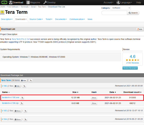
To download Tera Term for Windows 10, follow this link, and click on the .exe file for the latest release (see figure 2). You will be redirected to another page, where your download will begin automatically. Once the download is complete, launch the application from the downloads folder, and follow the instructions to configure Tera Term on your device. You do not need to select or deselect any of the optional packages.
Connecting to the Comb Module
Once Tera Term is finished installing, launch the application. You will be shown a window like the one in figure 3. Check the “Serial” option and select the COM Port associated with your comb module. To find the correct COM Port, open the Device Manager, and expand the “Ports (COM & LPT)” drop-down. Unplug the USB Type-B to Type-A connector while watching the list of devices. The COM Port of the SVS FFC Module will be the one that disappears and re-appears. Click “OK” in the window.
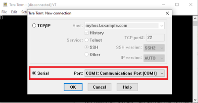 Fig. 3: Initial Tera Term Window
Next, navigate to “Setup –> Serial Port…” and change the “Speed” drop-down menu from 9600 to 115200 and click “New Setting” to save. Then navigate to “Setup –> Terminal…” and change both “Receive” and “Transmit” from “CR” to “CR+LF”. Check “Local Echo” and then click “OK” to save the settings.
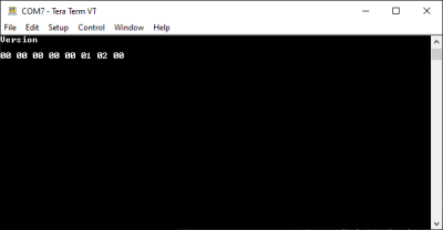 Fig. 4: Verify that the SVS FFC Module is communicating with the Version command
Finally, type Version into the terminal and hit enter to verify communication with the SVS FFC Module as shown in figure 4. If the connection was successful, the return will be 8 bits showing the firmware version on the SVS FFC Module.
Sending Commands
With the Serial Command interface set up now, you will be able to send individual commands to the SVS FFC Module by typing them directly into the terminal. During the initial verification and test setup of the SVS FFC Module, it is recommended to use the terminal interface as shown in this guide, though later it may be beneficial to write your own serial command scripts.
FPGA Control
The SLICE-FPGA dual-channel Offset Phase Lock Servo can be used to phase lock ƒCEO and ƒopt. Locking fopt requires a reference CW laser and heterodyne setup (such as a 50:50 beam splitter and DWDM filter). The stability of the lock will depend on the reference laser used. All performance data is collected with a Rio Planex laser.
Installing FPGA Software
To use the FPGA software you must download both WinPyton and the software itself. To install the software, follow this link, click on “FPGA Software.zip”, and then press the download button. Make sure to save the zip file to your computer, and not just open it. Extract the file to a directory which will be convenient to navigate to using a command line.
Next, install WinPython version 2.7.10.3 by following this link and choosing the appropriate file for your system. Do not download the latest version of WinPython, as it will not work with the FPGA software.
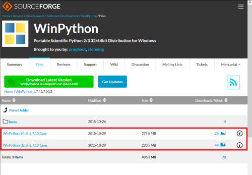 Fig. 5: Download Screen for WinPython. Choose one of the two options from within the red box.
To check which of the two files is correct for your system, go to the windows search bar or hit the “Windows” key on your keyboard, and type “About your PC”. The window shown in figure 6 will appear, and you can find whether your computer is 32-bit or 64-bit. Choose the corresponding file from the download list in figure 5.
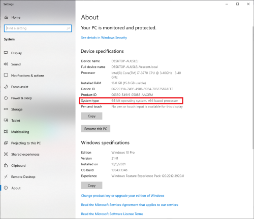 Fig. 6: Check whether your operating system is 32-bit or 64-bit
Locking the SVS FFC Module
Before locking, it may be beneficial to familiarize yourself with the full list of API commands for the SVS FFC Module, which can be found here, as well as the front and rear panel connections, which can be found here. It is also important to note that, aside from those set in the FPGA software, all PID parameters come preset and should not need to be adjusted.
Connections
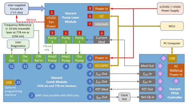
After initial verification of the SVS FFC Module with Tera Term, the system as a whole can be connected as shown in figure 8. The USB “Optional Programming Interface” labeled “13” should already be connected to a Windows 10 machine, and should be left connected for the duration of this setup. Ensure that the FPGA remains off until Step 7. In general, do not power on any components of the system until explicitly instructed to do so. Failing to follow the correct start-up order may damage your system.
Step 1: Turn on TEC and HV PZT
In the Tera Term terminal window, type Tempset? 0 to check the setpoint temperature. If the return is not within the normal operating range of 20°C to 30°C, change the setpoint temperature to 25°C by typing Tempset 0 25.0. Next, enable the oscillator cavity TEC by sending the Control 0 3 command and turn on the HV PZT by sending Control 1 3. Finally, wait 5-10 minutes for the TEC to stabilize. The current temperature of the TEC can be monitored with the Temp? 0 command, and the error between the temperature and the setpoint temperature (in mK) with Terror? 0. The TEC is stabilized when Terror? 0 returns a value less than 0.1 mK.
Step 2: Power Pump Diode Boards
The actual I2C implementation of the Pump Diode boards has been left to the user, but in general it is at this time that the pump diode boards should be powered on and temperature stabilized. Do not supply current to the diodes themselves until their temperature has stabilized. If connections have not been made already, ensure that the OSC Out (Pump 1) and any EDFA Amplifiers (Pumps 2 and 3) on the Pump Diode Board have been connected to the SVS FFC Module as shown in figure 8.
Step 3: Power and Connect CW Laser
It is essential that the SVS FFC Module be locked to an external reference, which should now be powered on and connected to the SVS FFC Module if it was not connected already. Follow the start-up procedure for your given CW reference laser.
Wrap this: The maximum power input for CW in is 2mW. Exceeding this input power may damage your system.
Step 4: Mode Lock the SVS FFC Module
Connect the OSC Mon output to a spectrum analyzer or OSA. Check that the OSC pump diode's current setting is within the specified range of your CoC, and then enable current to the OSC pump. It is recommended to start near the middle of the specified current range, and then to increase the current until CW breakthrough can be observed on the spectrum in the form of a narrow peak forming above the broader curve. Once CW breakthrough is achieved, lower the current roughly 10 mA to give the system room to modulate for a lock.
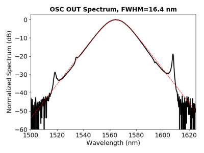 Fig. 9: Example spectrum showing a mode locked system
Wrap this: Should the current be increased too far, it is possible to enter a different mode locking regime as shown by the spectrum suddenly becoming visibly narrower than before. Should this occur, incrementally lower the current until the laser jumps back into the previous, wider, mode locking regime. There is a slight hysteresis in this process, so it is likely that you will need to lower the OSC pump current past the current where the regime changed and nearer the middle of the specified current range.
Step 5: Verify Supercontinuum
Now that the system is mode locked, switch the monitored output to SC Out and change your Spectrum Analyzer or OSA's window to span the 1-2 micron wavelength region. Verify that the supercontinuum of your system matches that shown in your CoC. An example supercontinuum can be seen in figure 10
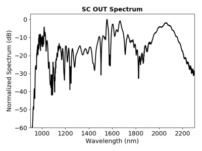 Fig. 10: Example supercontinuum of the SVS FCC Module system
Step 6: Verify RF Output
Connect the RF Mon output to a spectrum analyzer to verify that the RF output matches what is shown in your CoC. Set the spectrum analyzer's span to 1kHz-2GHz and look for a series of equally spaced peaks as shown in figure 11. The first peak is the repetition rate of your SVS FFC Module, and the rest are harmonics.
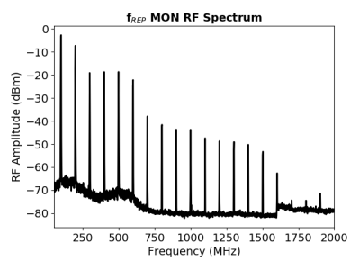 Fig. 11: Example RF spectrum from the SVS FFC Module system with 100 MHz repetition rate
Step 7: Power On and Set Up the FPGA
After verifying the outputs of the SVS FFC Module, make connections to the FPGA as shown in figure 8 if they have not been made already, and turn the FPGA on. The FPGA will apply a modulation current to the oscillator, which if not accounted for properly in Step 4 may cause your system to leave its mode lock regime. Open a WinPython terminal and navigate to the …\“FPGA Software”\“GUI and Firmware” folder then run python XEM_GUI3_VPv4.py to launch the FPGA software. A window will appear asking for initial configuration settings as shown in figure 12. Ensure that “superlaserland_v12.bit” is selected for Fimware File, and check the “Send Firmware” and “Internal Clock (100 MHz)” boxes.
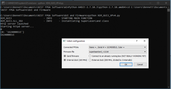 Fig. 12: Configuration window shown before FPGA software launches
Once the FPGA software launches, navigate to the “Filter Settings” tab and select “Narrowband (6MHz) for both channels. Finally, navigate to the “CEO Lock” tab, and input the PID parameters given in your CoC, then repeat for the “Optical Lock” tab.
Slow Loop Feedback
Slow loop functionality will be provided in a near-term software update.
- Open your computer’s device manager from the control panel and find the COM port number for “STMicroelectronics”. Never assume that this number is the same as previous times. (If it doesn’t appear, make sure your computer is connected to the FFC.)
- Navigate to the “Slow Loop” tab in the GUI and enter the COM port number into “FFC COM Port”.
- The PZT setpoint is set to an intermediate value (50V) to keep the servo from railing. This can be adjusted if desired.
- Click “Activate Temperature Slow Loop”.
guide.


