This is an old revision of the document!
Table of Contents
FFC-100 Fiber Frequency Comb Manual
Model No. FFC-100-100 and FFC-100-200
Document Last Updated on 2022/09/21 15:26
Please read Limited Warranty and General Warnings and Cautions prior to operating the FFC-100.
Links
Click here for the main manuals page.
Click here for the FFC-100 Quick Start Guide.
Click here for the FFC-100 API.
Click here for the FFC-100 web page.
Click here for the Github page for FFC-100 Firmware revisions
Click here for the Github page for FFC-100 FPGA Firmware Revisions
Click here for the latest version of WinPython
Click here for the Github page for FFC-100 Upgrade Utility
Click here for the RPM-100 FPGA Locking Manual
Please check back for added functionality. Contact sales [at] vescent [dot] com for questions and corrections, or to request added functionality.
Quick Start
Jump to the FFC-100 Spec Sheet.
Jump to General FFC-100 Operation.
Jump to Locking the FFC-100 using the FPGA Software.
Description
The FFC-100 is Vescent Photonics' premier turn-key, deployable fiber frequency comb. It is ideal for use in an optical clock, dual-comb spectrometer, or to transfer the precision of an optical frequency reference to another part of the spectrum. It boasts in-loop fractional instability of <10-17 on fCEO and <10-18 on fopt.
Purchase Includes
- FFC-100 rack-mountable Fiber Frequency Comb module
- Power cord for your country (if known)
- Instructions on how to download & install control software
- Final Test Documentation
- Certificate of Conformity (CoC)
- Other items depending on specific configuration
List of Warning Symbols
 | Warning. Pay special attention to procedures and notes. If procedure is not followed carefully, damage to the FFC-100 or devices connected to it may occur. |
 | Potential for electrical shock hazard. |
Absolute Maximum Ratings and Power Input
Note: All modules designed to be operated in a laboratory environment.
The FFC-100 employs a proprietary design hybrid power supply that is both low noise and capable of accepting a range of AC input line voltages. It will accept input line voltages within the ranges shown in table 2.
| Parameter | Value | Units |
| Input Line Voltage | 100-240 | VAC |
| Frequency | 50-60 | Hz |
| Phase | 1 phase | |
| User-serviceable fuse1) | T 2.0 A L 250V | |
Proper Usage
 | If this instrument is used in a manner not specified by the manufacturer in this manual or other relevant literature, protection provided by the instrument may be impaired. |
| Successful implementation of the FFC-100 depends critically on the design of the whole system: FFC-100, phase locking electronics, and any references to which the FFC is locked or vice versa. |
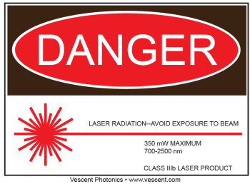
The FFC-100 Supercontinuum output, when collimated and focused, is a Class 4 laser device. In order to be in US FDA compliance for driving lasers:
- There is a 5 s delay between turning on the current and the current beginning to flow. During this period, a warning light will flash on the front panel of the FFC-100.
- The key switch on the rear panel must be in the on position (where you cannot remove the key).
- The interlock connector on the rear panel must be shorted either with the 50 Ω terminator supplied with the device or via an external circuit including, for instance, a (closed) entranceway.
If either the key switch is deactivated or the interlock is opened while the system is operating, the FFC-100 will stop delivering current to all lasers and the Laser State window will flash red with INTERLOCK displayed. In order to resume normal operation, interlocks must be restored to their operational state and the Laser State window must be touched to clear the tripped interlock.
Do NOT use a Fiber scope to view any outputs while FFC-100 is in operation.
Always be sure to operate FFC-100 within its recommended temperature and current ranges. As with any diode laser and controller, improper usage can cause irreparable damage to internal diodes.
Notice
 | Do not block the airflow vents on the side of the chassis or the fan inputs & outputs on either the FFC-100 or the SLICE-FPGA. |
| The mode-lock indicator on the GUI front panel cannot detect CW breakthrough. Keep the oscillator current within the range specified in your product's final test documentation or CoC. |
Acronyms, Abbreviations, & Definitions
| Jargon | Meaning |
| CoC | Certificate of Conformity- collection of performance data for a specific unit as measured by the factory during the manufacture of the unit. Final Test report. |
| EDFA | Erbium Doped Fiber Amplifier - the type of fiber amplifier used in the FFC-100. |
| SC | Supercontinuum - the octave spanning, spectral broadened light used to perform self-referencing. |
| PM FC/APC | Polarization Maintaining Fiber Channel/Angled Physical Contact connector. |
Specifications
| Performance2) | |||
| Parameter | Value | ||
|---|---|---|---|
| ƒopt Locked Phase Noise | <500 mrad | ||
| ƒCEO Locked Phase Noise | <3 rad | ||
| In-Loop Allan Deviations | <10-17 | ||
| Optical IO | |||
| Input / Output | Type | Current | Power |
| OSC Out | PM FC/APC | 225-445 mA 3) | 130 µW |
| EDFA Out | PM FC/APC | 1575 mA 4) | 8.8 mW |
| SC Out | PM FC/APC | 1575 mA 5) | >50 mW |
| ƒopt In | PM FC/APC | – | < 1.5mW maximum |
| RF IO | |||
| Input / Output | Type | Output | |
| ƒrep MON | SMA | >-3 dBm at rep rate 6) of comb | |
| ƒopt MON | SMA | >-10 dBm, >50 dB SNR beat note between comb and optical input | |
| ƒCEO MON | SMA | >-30 dBm, >30 dB SNR beat note inherent to self-referenced frequency comb | |
Features
Front Panel
An image of the front panel is shown in figure 2. The functions and connections are as follows:
- Oscillator Monitor Port (FC/APC)
- EDFA Monitor Port (FC/APC)
- Supercontinuum Output Port (FC/APC)
- Input Port for foptical detection (FC/APC).
- SMA monitor for FFC-100 Repetition Rate frep
- SMA monitor for foptical
- SMA monitor for Carrier Envelope Offset frequency fCEO
- Parameter input adjustment rotary knobs
- Menu control and monitor for Oscillator Cavity
- Menu control and monitor for internal Pump Lasers
- Mode Locked indicator light. Green indicates mode lock.
Rear Panel
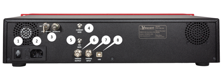
An image of the rear panel is shown in figure 3. The functions and connections are as follows:
- Main On/Off power switch
- AC line power in7)
- User-serviceable fuse (T 2.0 A L 250V)
- Interlock Key receptacle and Door Interlock BNC with 50Ω terminator
- SMA Input for current modulation (typically through FPGA)
- SMA Input for PZT modulation (typically through FPGA)
- Output trigger (BNC)
- Input trigger (BNC)
- USB port (Type B)
Operation
Screen Navigation
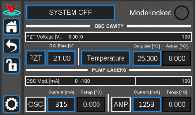
When presented with a given view, it is possible to select the functionality or edit the values in a field bordered in blue. When a particular field is actively being edited, its border will change to yellow. If a field is selected, but not changed after 60 seconds the field will flash red and become deselected without changing its value. The Home Screen of the FFC-100 is shown in figure 4. From the Home screen, control of the laser state, oscillator cavity, and pump lasers can be accessed by the user.
In general, the status displayed in an editable field is the current status and not the result of touching the button. Touch the field to select a new value/status. For instance, in figure 4 the FFC-100 laser output is off. Touching the SYSTEM OFF button will allow the FFC-100 to be placed into STANDBY, and then subsequently for the laser output to be powered on.
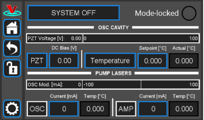 Fig. 4: Home screen of FFC-100
Control Bar
On the left edge of the screen is the Control Bar. At any given time, these buttons will have the following effect.
Home Button
 Fig. 5: Home button
Returns to Home Screen (figure 4).
Back Button
 Fig. 6: Back button
Returns to previous screen. Changes will be lost if not accepted before using the Back button.
Lock Button
 Fig. 7: Lock button (shown in unlocked mode)
Locks out further modification of parameters. Touch to lock or unlock parameter entry. There are some parameters with values which can be changed while the system is locked, such as the PZT range, but in general parameters which control a state or value, such as the set point temperature of a pump diode, cannot.
System Settings Button
 Fig. 8: System settings button
Enters screen for system settings control (brightness, volume, etc.).
Entering Values
In most instances, there are two methods for entering parameter values: the physical rotary knobs on the front panel and the pop-up keypad on the touch screen. When using the knobs to change the value of a parameter, changes take effect immediately. When using the keypad, changes do not take effect until the enter key is pressed.
In order to afford maximum resolution, the least significant digit will not necessarily change to precisely your target value and will be coerced to the nearest acceptable value, which is limited by the digitization scheme for the set point. For instance, you may change the oscillator cavity set point temperature to 17.000°C, but the closest allowed digitized value may be 16.999°C.
Rotary Knobs
If you touch an editable field for a brief moment, a cursor will appear as a line under one of the digits of the parameter value. By turning the right knob, it is possible to increase (cw) or decrease (ccw) the value of the underlined digit. Turning the left knob will change which digit is editable (cw to move to the right and ccw to move to the left) as indicated by the underline.
Keypad
If you touch and hold an editable field such as the set point temperature, a numeric keypad will appear as seen in figure 9. You can then enter the full value of the desired parameter with this keypad.
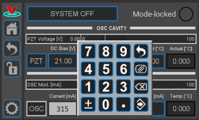 Fig. 9: Pop-up Keypad
The action initiated by each button is described below.
Escape
Clear
Delete
Enter
Home Screen
The Home screen gives access to control of the FFC-100's operational state, as well as several parameters pertaining to the FFC-100's internal oscillator cavity, and its pump diodes. It is divided laterally into three sections. The top third of the screen includes a button to select the FFC-100's state, as well as an indicator for whether the laser is mode locked. The middle third of the Home screen is dedicated to controlling the FFC-100's internal oscillator. From here the range and DC bias of the PZT, and the temperature of the cavity can be selected. The bottom third of the home screen allows the user to control the current supplied to the two internal pump diodes: OSC and AMP, which pump the Oscillator and Amplification fibers respectively. The temperature of each pump diode is displayed directly to the right of their current.
Turning the FFC-100 On/Off
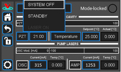
Using the button in the top left of the home screen, the FFC-100 can be placed into one of three states: System Off, Standby, and Laser On. After powering on, the FFC-100 will always be in the System Off state, which indicates that it is not temperature controlling, or supplying current to any of its internal diodes or the cavity PZT. To begin using the FFC-100, touch the System Off button and select “Standby” from the pop-up menu. Placing the FFC-100 into Standby mode allows it to stabilize its internal temperatures. You will notice that, while in System Off mode, the Laser On option is grayed out in the menu and is not able to be selected. To turn the FFC-100 all the way on and begin lasing, it is necessary to first wait for all internal temperatures to reach their setpoints and settle to within their locked range. After temperatures have stabilized, indicated by their field changing from yellow to green, touch the Standby button and select “Laser On” from the pop-up menu. After a mandatory 5 second delay, during which the Laser On button will flash, the FFC-100 will begin lasing and shortly thereafter the mode locked indicator light will turn green and the FFC-100 is ready to be used. For a step-by-step guide, follow the instructions below.
- Once the temperature servos have stabilized and “Standby” has stopped blinking, touch the “Standby” drop-down menu (figure 16) and select “Laser On” (figure 17). The FFC should commence lasing and the Mode-locked indicator should turn green (figure 18).
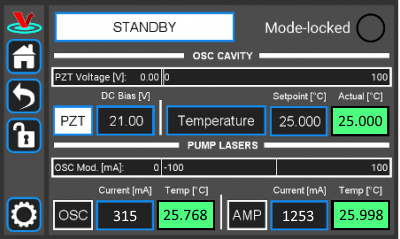 Fig. 16: The FFC-100 GUI: in Standby mode
 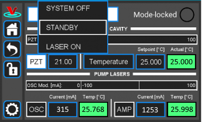 Fig. 17: The FFC-100 GUI: Standby to System On
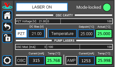 Fig. 18: System On
To turn the FFC-100 off, place it back into standby mode and wait a moment. The FFC-100 will place itself back into System Off mode automatically, after which it is safe to power the system down. Do not change the state of the FFC-100 directly from “LASER ON” to “SYSTEM OFF” or flip the rocker switch on the back while the laser is on. Doing so may result in damage to your system.
Changing the PZT range and DC Bias
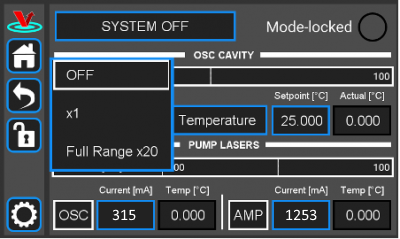
The range of the cavity PZT can be toggled between OFF, 1x (0-10V), and Full Range 20x (0-100V) by touching the PZT button in the middle of the home screen and selecting an option from the pop-up menu.
A DC bias can also be applied to the PZT so long as it is within the selected range. With the 20x Full Range selected, a DC bias between 0V and 100V can be applied. For best performance it is recommended to place the DC bias at, or near the middle of the selected range setting. In general, it is easier to lock the comb while the PZT range is “Full Range 20x”, but there is slightly lower noise while it's in “1x” mode. When first setting up your FFC-100, it is recommended to use “Full Range 20x”.
Changing Cavity Temperature
In addition to PZT controls, the middle third of the home screen allows control over the temperature of the oscillator cavity, and several of the parameters of the PID temperature servo. To set a new temperature, touch the “Setpoint [°C]” button and enter a value either with the rotary knobs, or the pop-up Keypad as described here. Changing the cavity temperature is not generally necessary, as factory presets will allow normal use of the FFC-100. However, if you are trying to hit a specific frequency (to synchronize two combs, for instance), changing the temperature is the primary method of making this adjustment.
Although they are factory set for each FFC-100 individually, to view or change the PID parameters of the oscillator touch the “Temperature” button to switch to the Temperature Screen, and then select “Settings”–>“PID Params” to bring up the PID control menu. From here, each component of the PID loop can be individually adjusted, or toggled On/Off.
Changing Pump Diode Current
The current supplied to each of the FFC-100's two pump diodes is controlled from the bottom third of the Home Screen. The OSC diode pumps the fiber inside the Oscillator Cavity in the process of generating the femtosecond pulsed laser, and the AMP diode pumps the amplification fiber outside of the cavity. The current supplied to each of these diodes can be set by touching their respective fields, and entering a value using either the rotary knobs, or the Input Keypad menu as described here.
Temperature Screen
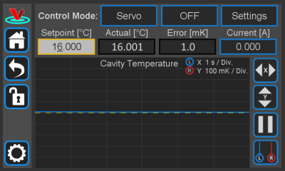
To access the Temperature Screen (figure 20), press the “Temperature” button in the middle third of the home screen. From this screen there are several options which provide fine-tune control of the Oscillator Cavity, as well as a rolling plot of the error signal between the FFC-100's cavity setpoint temperature, and its measured temperature. It is also possible to adjust the setpoint temperature of the oscillator cavity by touching the “Setpoint[°C]” field, and entering a new value with the knobs, or the Input Keypad as described here. By touching the “Current [A]” field, the value it displays can be changed to either “Power [W]” or “Voltage [V]”.
Servo Control
By touching the “Servo” field at the top of the Temperature screen, it is possible to toggle between the FFC-100's automatic “Servo” mode, and a user controlled “Manual” mode. The default setting for this field is “Servo”, from which the on-board computer will attempt to servo the temperature of the oscillator cavity to its setpoint temperature using the PID parameters it is given. “Servo” mode performs with sub-milikelvin stability and is factory tuned to suppress temperature perturbations using the Ziegler-Nichols method. With “Manual” mode enabled, the user is able to directly change the current supplied to the TEC which controls the temperature of the Oscillator Cavity. The default setpoint current is 0A, and can be changed by touching the “Setpoint [A]” field and entering a value using the rotary knobs, or through the Input Keypad menu as described here, though for this method it is recommended to use the rotary knobs.
Exercise extreme caution while tuning temperature in manual mode. The FCC-100 will supply its setpoint current to the Oscillator cavity's TEC continuously while the servo is enabled. Temperature runaway can damage the oscillator cavity if maximum and minimum temperature are not set correctly.
Servo Enable
The FFC-100's temperature servo can be enabled by touching the button labelled “OFF” directly to the right of the “Servo” button (figure 20). Doing so will immediately engage the servo loop and begin supplying current to the TEC which controls the temperature of the Oscillator Cavity. The text on the button will change to “ON” and its background color will change from black to white. To disable the servo, simply touch the button again.
Settings
The “Settings” menu has two options: “PID Params”, and “Temp Limits”, which can be accessed by touching the corresponding fields in the Settings menu. The functionality of each option is described below.
PID Params
The “PID Params” option brings up a menu from which the PID parameters of the oscillator cavity's temperature servo loop can be adjusted, or toggled On/Off. To do so, touch the field corresponding to the desired value, and enter a new value with the rotary knobs, or the pop-up Keypad menu as described here. Each PID term can be controlled, or toggled individually in this way. Additionally, by touching the “Slew [°C/min]” field, a limit can be placed on the speed at which the FFC-100 servos the temperature of the cavity. In general, these settings are optimized and set in-factory for each FFC-100 individually, and should not need to be adjusted.
For written instructions on properly tuning this cavity see here, or a video tutorial here
Temp Limits
The Temp Limits option brings up a menu from which the Locked Range, Maximum Temperature, Minimum Temperature, and Shutoff Time can be selected. The Locked Range of the FFC-100s cavity temperature defines the ΔT range for which the FFC-100 will consider the measured actual temperature to match the setpoint temperature. The FFC-100 cannot be moved from “STANDBY” mode to “LASER ON” mode until the temperature of the oscillator cavity has reached its setpoint temperature. The Maximum Temperature and Minimum Temperature settings define the highest and lowest temperatures the FFC-100 will allow the oscillator cavity to reach before shutting off temperature control, and the Shutdown Time setting dictates how many seconds the temperature of the oscillator cavity is allowed to be higher or lower than the maximum or minimum temperature respectively before shutting off.
Temperature Error Graph
The main feature of the Temperature Screen is the rolling graph which plots the error signal between cavity setpoint temperature and measured temperature. This plot is always centered on the cavity setpoint, and its X and Y axes can be adjusted using the L and R rotary knobs respectively, or by touching the X axis adjust, or Y axis adjust buttons to the right of the plot.
To pause the plot, touch the pause button directly below the Y axis adjust button. Doing so will place two vertical line cursors on the plot, which can be moved using the L and R rotary knobs, or by touching them on the screen and dragging them to the desired location. The distance (time) between the cursors Δt is displayed at the bottom of the plot. These cursors can also be accessed while the plot is live by touching the cursors button. To unpause the plot, press the play button, which replaces the pause button while the plot is paused.
The functions of the four buttons to the right of the plot are described below:
System Settings
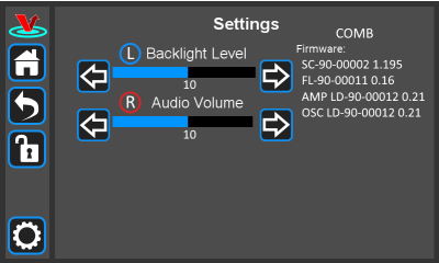
The FFC-100's Settings Screen (figure 21) can be accessed by touching the gear icon in the control bar, and gives access to the FFC-100's current firmware version, as well as options for changing its screen brightness and its volume. To change the screen brightness, either turn the Left (L) rotary knob, or touch the arrows on either side of the brightness bar. To change the volume either turn the Right (R) rotary knob, or touch the arrows on either side of the volume bar. The version of the Firmware currently installed on the FFC-100 is displayed in the top right hand side of the Settings Screen.
Repetition Rate Tuning
The repetition rate of the FFC can be tuned by adjusting cavity temperature, which has a transfer function of >2 kHz/°C. The intracavity PZT affects repetition rate as well, but it has a small tuning range (<1 kHz) and as such should be used solely for locking fopt, which is its main function. While it is not necessary to change the repetition rate of the FFC-100 for normal use, it can be helpful in certain set ups, such as when synchronizing two Frequency Combs.
Initial Set-up
- Download and install software according to instructions found here.
- Turn on the power to the Fiber Frequency Comb (FFC) and the FPGA, as well as the reference laser.
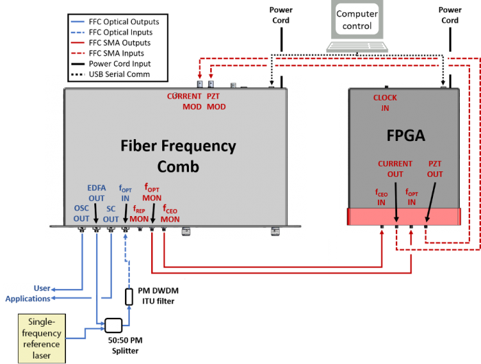 Fig. 22: FFC-100 electrical and optical connection diagram (Click for larger image)
Example Spectra
The following are example spectra of several of the FFC-100's outputs. Data for these spectra were taken with a RIO Planex laser in normal, laboratory conditions. Similar measurements for your specific FFC-100 can be found in the CoC shipped with your unit.
OSC Out
This is a PM FC/APC fiber output that is a direct monitor of the fiber oscillator. A power output of 130 μW was measured at an operating oscillator current of 430 mA, as well as the optical spectrum shown in figure 23 with 14.5 nm of bandwidth.
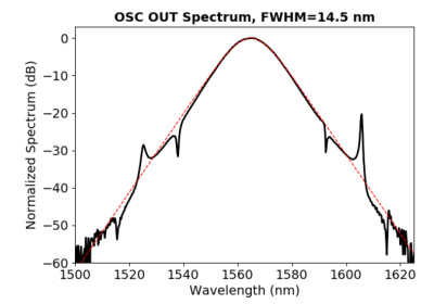 Fig. 23: OSC Out Spectrum from FFC-100
EDFA Out
This is a PM FC/APC fiber output and is a direct monitor of the fiber amplifier. A power output of 8.8 mW was measured at an operating amplifier current of 1575 mA as well as the spectra shown in figure 24.
Supercontinuum Out
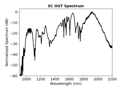
This is a PM FC/APC fiber output that is the direct output of the fCEO detector module. A power output of 52 mW was measured at an operating amplifier current of 1575 mA. figure 25 shows the power/wavelength relationship of the output across its octave span.
Repetition Rate
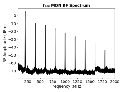
This is an SMA monitor port of the frequency comb repetition rate with the RF spectrum shown in figure 26. The comb reaches a repetition rate of 200 MHz at an oscillator cavity temperature of 20.1°C. The fundamental repetition rate tone has an amplitude > 0 dBm.
Optical Heterodyne
This is an SMA monitor port of the frequency comb fOPT RF parameter with the RF spectrum shown in figure 27. The beatnote exhibits an SNR of > 50 dB in a 100 kHz RBW and 10 kHz VBW.
 Fig. 27: Optical Heterodyne between CW RIO Planex and FFC-100
Carrier Envelope Offset
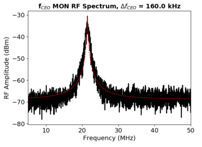
This is an SMA monitor port of the frequency comb fCEO RF parameter with the RF spectrum shown in figure 28. The beatnote exhibits an SNR of >35 dB in a 100 kHz RBW and 10 kHz VBW. The locked full width half max linewidth of fCEO was measured to be 160 kHz.
FPGA Control
For locking the FFC-100 with the Vescent RPM-100 Module, click here. Otherwise, if using the SLICE-FPGA, follow the instructions below.
The SLICE-FPGA dual-channel Offset Phase Lock Servo can be used to phase lock ƒCEO and ƒopt. Locking fopt requires a reference CW laser and heterodyne setup (such as a 50:50 beam splitter and DWDM filter). The stability of the lock will depend on the reference laser used. All performance data is collected with a Rio Planex laser.
If you have not already done so, install Python and the FPGA software for controlling the SLICE-FPGA dual Offset Phase Lock Servo.
Software Startup
- Open a WinPython command window and navigate to the folder “GUI and Firmware”. Note that a WinPython command window is not the same as the Windows native CMD command line.
- Start the SLICE-FPGA control GUI by typing “python XEM_GUI3_VPv4.py”, figure ##).
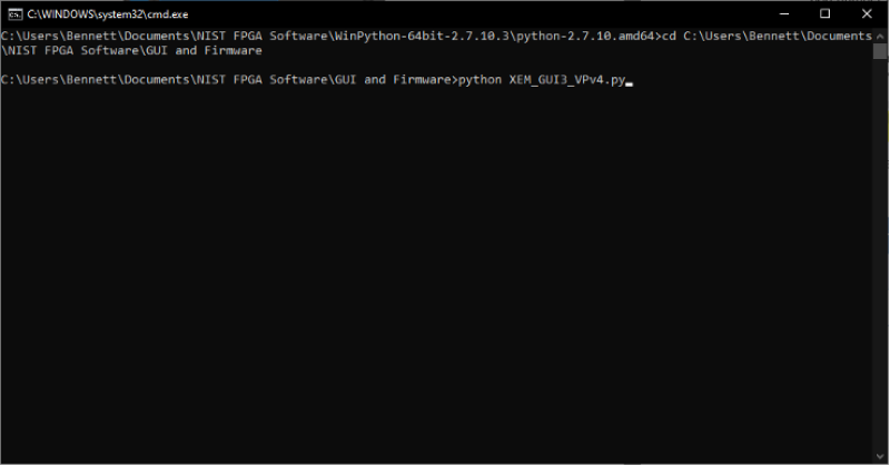 Fig. ##: Start FPGA GUI from Terminal
- A start-up menu should appear (figure ##). Make sure “superlaserland_v12.bit” is selected and select an appropriate clock option: internal clock will use the FPGA's on board clock for timing, whereas external clock can be selected to allow synchronization between devices with a separate timing device. If you are unsure which to select, choose Internal Clock. Leave all other settings as default and press OK.
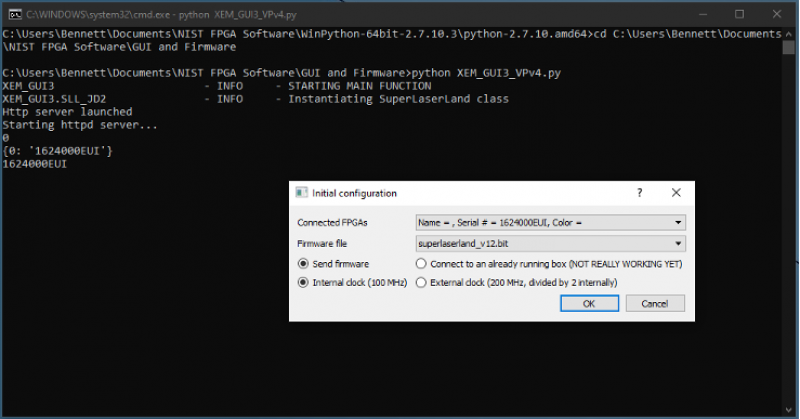 Fig. ##: FPGA GUI Start Screen
- Navigate to the Filter Settings tab and select “Narrowband (6MHz)” for both DDC0 and DDC1 (figure ##).
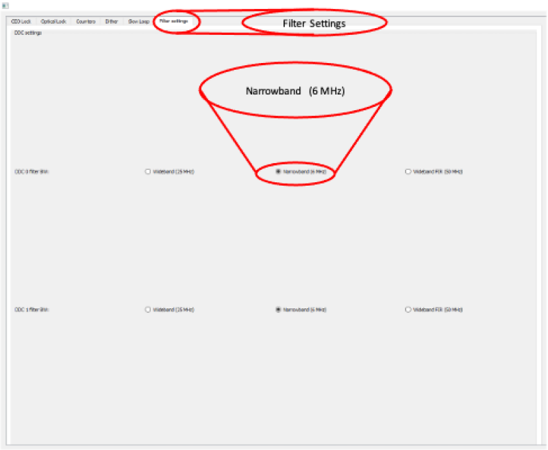 Fig. ##: Set Loop Filter Bandwidth
CEO Lock
This tab of the FPGA software allows the user to lock ƒCEO, and to tweak the parameters of the lock for best performance. To lock ƒCEO, first ensure that there is a visible beatnote displayed on the “Spectrum” plot. This will be an obvious peak above the noise floor which responds to adjustments of the “Offset DAC 0 [V]” slider. If a beatnote cannot be identified, check that the FFC-100 is mode locked. Once a beatnote has been identified, adjust the “Offset DAC 0 [V]” slider such that the Baseband IQ plot is roughly circular, or the identified beatnote is between two of the dips on the spectrum plot corresponding to a bandpass filter (figure ##). It is important to note that, while the “Offset DAC 0 [V]” slider range displays values between 0 and 8V, the DAC itself is incapable of going higher than 4V, so make sure that the slider is between 0V and 4V while making this adjustment. If the slider is placed higher than 4V it will not damage the system, but it might cause problems with obtaining a lock.
 Fig. ##: Offset DAC location and Beatnote Example
To lock the system, simply click the checkbox at the top of the screen labeled “Lock” and the system should snap fairly quickly into a lock. If the system does not lock, and immediately rails, uncheck the “Lock” checkbox, change the sign of the VCO by selecting the opposite “VCO sign” checkbox to the right of the “lock” checkbox, and try again. If the system still does not lock, check that your PID parameters are set to, or near to, the values given in your CoC and shipped with the system. If there is still no lock, check the Troubleshooting section for potential solutions.
 Fig. ##: Offset DAC location and Beatnote Example
Once a lock has been obtained, the green plot of phase noise on the “Phase Noise PSD, std dev =” plot will show a dramatic reduction in noise from ƒCEO's unlocked state. This number is a good characterization of the stability of your lock. A good lock of ƒCEO is indicated by an integrated phase noise PSD less than 2 rad, but this value can be pushed down even further by adjusting the PID settings of your FFC-100.
Before adjusting the PID parameters, uncheck “Auto-refresh” at the top of the screen. Change the value of “RBW: 576 Hz; Points:” to “3e6”, then recheck “Auto-refresh” (figure ##). This will update the graph to plot more points and give a more accurate representation of the phase noise. It is important that Auto-Refresh be unchecked before making this adjustment, however, as doing so while the plot is refreshing may cause the FPGA software to crash. If this happens, simply relaunch the software and start again.
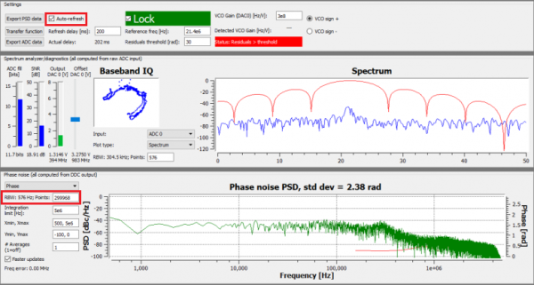 Fig. ##: Resetting the RBW and Plot Points to get more accurate phase noise plot
The PID settings provided with the FFC-100 on delivery are intended to give a relatively stable lock out of the box in normal laboratory conditions. If at any point the PID parameters are adjusted too far out of range and the FFC-100 is not locking, resetting them to ship parameters will allow you to quickly get back to a baseline lock. The PID parameters shipped with the FFC-100 can be found in section 6 of CoC delivered with your FFC-100.
Adjustment of the PID settings to obtain a tighter lock can be done from the bottom section on the CEO lock tab (figure ##). Begin by resetting the parameters to ship settings, and then adjust Kp by clicking on its slider, then pressing the arrow keys on your keyboard. It is possible to move the slider with the mouse, or by typing in a value, but the keyboard arrow keys will provide the most fine tuned control of the value. Change the value up or down and watch the number displayed in the Phase Noise PSD plot to ensure that the changes are reducing integrated phase noise. After optimizing Kp, if the integrated phase noise is still too high, go through the other PID parameter sliders underneath until you have reached your desired noise optimization. In general, small adjustments of Kp will provide the largest change in integrated phase noise, assuming that all values begin close to ideal.
Optical Lock
This tab allows the user to lock and tweak ƒopt: the beatnote between a tooth of the FFC-100 and the reference laser. The process for locking ƒopt is nearly identical to locking ƒCEO, except that there is an extra slider (Offset DAC 2) on the screen. It has no effect on the system, and can be left alone. Begin by adjusting the “Offset DAC 1 [V]” slider until the Baseband IQ is roughly circular, or the beatnote is positioned between two dips on the Spectrum plot corresponding to a band pass filter. Once the beatnote is centered, or the Baseband IQ is roughly circular, check the “Lock” checkbox at the top of the tab and wait a moment. The Phase Noise PSD plot will indicate whether your system is locked by showing a dramatic reduction in noise, and integrated phase noise. If your system is railing, change your VCO sign by selecting the opposite “VCO sign” checkbox to the right of the “Lock” checkbox. To optimize your lock, follow the instructions for adjusting PID settings given in the CEO Lock section.
On both the CEO Lock, and Optical Lock tabs, it is possible to change what is being plotted on the Spectrum graph in the Spectrum analyzer/Diagnostics bar. To do so, simply click on the “Plot type:” drop down menu and choose what you would like to plot. The options for this menu are: Spectrum, Time: raw input, Time: phase, Time: IQ, and Time, IQ synced. Choosing any option besides “Spectrum” will change the units on the bottom of the plot from Hz to seconds, and give a live plot of the value selected in the time domain. The same can be done with the Phase noise PSD plot in the Phase noise bar by clicking on the drop down menu in the top left hand corner of the bar (figure ##). The options for the Phase noise PSD plot are: Frequency (Freq), Phase, and time domain versions of each respectively. Other options for this plot include setting the outer limit for PSD integration scalable X and Y axes, and averaging. When taking a measurement of Phase noise or integrated PSD, it is recommended that the Averaging field be set to no less than 10.
 Fig. ##: Several options are available for how the Phase noise PSD plot is displayed.
To export data from the FPGA to a file, simply press one of the two export buttons in the Settings bar at the top of the tab(figure ##). If ADC data is being exported, a pop-up will appear and ask the user which ADC to export. The files will be saved in csv format to the Software and GUI folder from which the FPGA software is launched under data_exports. If this folder does not exist in that location, it will be created the first time data is exported.
 Fig. ##: Export ADC data, or the Phase noise PSD chart to CSV
Specific settings pertaining to the the way the loop filters are engaged to obtain the optical lock are available in the Loop Filters bar at the bottom of the Optical lock tab. It is not advised that the settings for this section be changed from their default values. Doing so could affect your ability to obtain a stable lock.
Dither
The Dither tab allows the user to add a modulation to the DAC current. Each DAC can individually be configured to be modulated at a specific frequency, integration time, and amplitude. A checkbox below these fields allows the user to select whether the modulation is always on (Manual On), always off (Manual Off), or to allow the computer to determine when the modulation is applied (Automatic).
Slow Loop
Firmware Version FL-V1.2
The Slow Loop tab allows the user to enable a slow servo temperature control of the intracavity PZT to prevent offset drift over long periods of time. It is recommended to always enable this feature after setting up a lock, as without it the PZT's offset voltage can drift to its rails over the course of several hours or even less. To enable the Slow Loop feature, simply fill in the “FFC COM Port:” field with the number corresponding to your FFC-100's COM port, choose the desired setpoint of the PZT, and press the “Activate Temperature Slow Loop” button at the top of the tab. For example, if your FPGA is on COM4, and your FFC-100 is on COM8, type “8” into the “FFC Com Port:” field and then press the button. This will bring up a command prompt window which will display information about the Slow Loop, such as the cavity temperature, and the current PZT setpoint. In general, it is best to select a setpoint near the center of the PZT's available range.
To determine the COM port of your FFC, open the Windows Device Manager on your PC, expand the “Ports (COM & LPT)” drop down, take note of which COM ports are listed, then unplug the FFC-100's USB connection. After the list updates, the COM port of the FFC-100 will no longer be listed.
Firmware Version G2-V1.2
Slow servo functionality is designed to allow indefinite FOPT locking times despite long-term drifts in the reference laser’s frequency outside the dynamic range of the FFC’s PZT feedback. This is achieved by slow temperature feedback to the oscillator of the FFC, which locks the PZT output voltage to a setpoint voltage near the middle of its dynamic range. To enable the slow servo, first lock FOPT normally, but set the DC offset as close to 3V as possible (PZT output range spans 0-60 V with 10V/V transfer function). Next, navigate to the home screen of the FFC-100 and press the “Slow Servo” button at the top of the screen
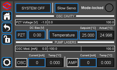 Fig. 29: The slow servo button is located on the home screen to the right of the System Off/Laser On button.
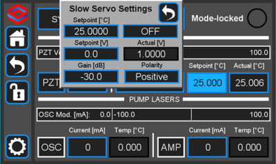
This will activate the slow servo but does not turn on the feedback. You can tell that the slow servo has been activated by the blue background on the “Setpoint [°C]” button.
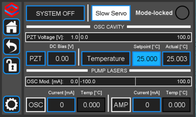 Fig. 30: When the slow servo is activated, the background of "Setpoint [°C]" turns blue
Next, press and hold the “Setpoint [°C]” button until the slow servo menu comes up. The menu allows a user to set the temperature setpoint as normal, and to set the voltage setpoint that the slow servo will try to keep constant by changing the temperature of the oscillator. We recommend setting this to 30V, which is right in the middle of the FFC-100's range. The gain comes preconfigured for each unit, but can also be changed through this menu (WE DO NOT ADVISE changing the gain without input from the Vescent technical staff). The polarity button will toggle the direction that the slow servo adjusts the temperature to keep the setpoint voltage constant (this will be preset by Vescent staff and should not be changed). Setting this to the incorrect value can result in temperature runaway. To change a value, simply touch the field to edit with the rotary knobs, or press and hold to bring up the keypad. To turn the slow servo on, press the “OFF” button. It should change to a white background which says “ON”. To turn it back off, simply press the button again.
While the slow servo is on, the color of the “Setpoint [°C]” button will indicate the difference between the setpoint voltage, and the actual voltage. If the difference is ≤ ±6V, the background will turn green. If it is ≥ ±6V, it will turn yellow, and if it is ≥ ±54V it will turn red. If the background is blue, this means the slow servo has turned off.
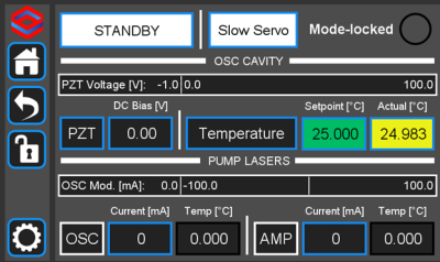 Fig. 32: The slow servo indicating the Voltage is within ±6V of the setpoint.
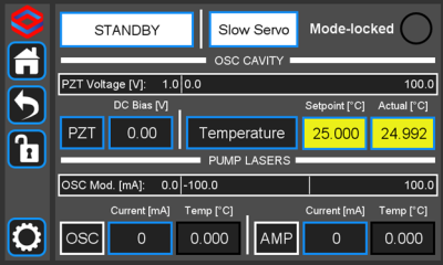 Fig. 33: The slow servo indicating the Voltage is more than ±6V away from the setpoint, but less than ±54V.
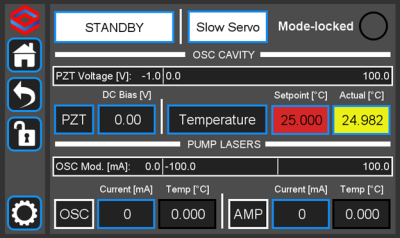 Fig. 34: The slow servo indicating the Voltage is more than ±54V away from the setpoint. This scenario is very unlikely.
Remember to shut off the slow servo, either by disabling it from the home menu or by pressing the On/Off button in the slow servo menu, when unlocking the FFC-100.
Troubleshooting/Common Issues
While we aim to make the user experience of the FFC-100 as simple and intuitive as possible, the fact remains that it is a complex instrument with many variables affecting its performance. Below you will find a list of common issues encountered while setting up and using the FFC-100, accompanied by suggested solutions. As always, if you have encountered a problem with one of our products please do not hesitate to contact us for customer support at [email protected] or by calling the number on our website.
FFC-100 Does not Switch to Laser On Mode
If, after placing the FFC-100 from “Standby” into “Laser On” mode, the button flashes for 5 seconds and then does not turn on, it is possible that the Interlocks on the back of the FFC-100 are not in the correct state. Check that both the Key, and BNC interlocks are correctly installed and in the right position and try again.
FFC-100 Does not Mode Lock Automatically
After placing the FFC-100 from “Standby” into “Laser On” mode, it should automatically mode lock within a few seconds, as indicated by the green light in the upper right-hand corner of the Home Screen. If, after several minutes the FFC-100 has still not mode locked, it is possible that you are experiencing hysteresis with the Oscillator pump diode. The solution for this problem is to gradually increase the current supplied to the OSC pump diode until the mode locked indicator turns green, and then turning it back down to prevent CW breakthrough.
ƒ(CEO) is not displaying a beatnote in the FPGA software
If you are able to lock ƒopt through the FPGA, but cannot see a beatnote while trying to lock ƒCEO, it is likely that your FFC-100 is not mode locked. Double check that the Mode Locked indicator on the Home Screen is Green, and that you are not seeing CW breakthrough. If the indicator is not green, it is possible that your FFC-100 is exhibiting some hysteresis, the solution for which is described in “FFC-100 Does not Mode Lock Automatically”.
CW Breakthrough
The easiest way to determine if CW breakthrough is occurring is to look at the OSC OUT port on an Optical Spectrum Analyzer. It will show up as a sharp peak near 1550 nm. If an OSA is not available, another possibility is to look at the fCEO spectrum – as oscillator pump power is increased, fCEO SNR will increase steadily until suddenly the linewidth of the beatnote will dramatically increase, and errant peaks will appear on the spectrum. These indicate the onset of CW breakthrough.

