
This is an old revision of the document!
Table of Contents
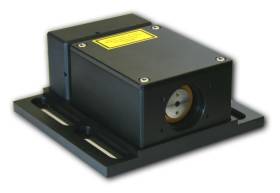
DBR Laser Module
Model No. D2-100-DBR
Document Revision: 2
Document Last Updated on 2021/08/26 14:26
Please read Limited Warranty and General Warnings and Cautions prior to operating the D2-100-DBR.
Description
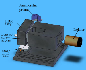
The DBR laser module is comprised of a distributed feedback (DBR) laser diode in a precision temperature-controlled housing with beam conditioning optics and an optical isolator. DBR laser diodes are fabricated with the feedback grating patterned directly over the gain section of the diode. They are highly immune to vibrations and by virtue of a very short cavity (~ 1 mm), they can be current tuned over more than 50 GHz. The result is a robust laser capable of very fast servo control for easy locking to atomic transitions. The module contains no moving parts or piezo-electrics and is therefore inherently robust and rugged.
DBR lasers have 2-3 times larger temperature and current tuning coefficients as compared to external-cavity diode lasers. Vescent carefully controls these parameters with two stages of temperature control and a precision low-noise current controller with fast servo input.
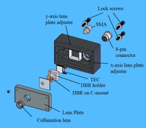
The DBR laser is collimated by a 0.68 NA lens mounted to a movable plate for pointing adjustments. The module also comes with a 35 dB optical isolator and a pair of anamorphic prisms. (Note that prior to fiber coupling we recommend a second stage of isolation.)
The temperature controllers use an 8-pin circular connector on the back of the DBR subassembly (see table 2 for identity of connectors). The injection current connection to the laser diode is through an SMA connector also on the back of the DBR subassembly.
The DBR laser chip is contained in a thermal package allowing temperature control between 15° to 30° C. Vescent can replace the package if it exceeds its lifetime.
Purchase Includes
- D2-100 DBR Laser
Absolute Maximum Ratings
Note: All modules designed to be operated in laboratory environment
| Parameter | Rating |
|---|---|
| Environmental Temperature | >15°C and <30°C |
| Environmental Humidity | <60% |
| Environmental Dew Points | <15°C |
| Stage 2 Temperature of DBR Laser Diode | >15°C and <40°C |
| Laser Diode Current | See datasheet included with your laser. |
The laser should never be operated at a temperature below the dew point temperature for your laboratory conditions. Condensation can form on the laser chip and/or mounting hardware resulting irreparable damage.
Specifications
| Min. | Typical | Max. | Units | |
|---|---|---|---|---|
| Wavelength | 767, 770, 780, 795, 852, 895, 1064, or 10831) | nm | ||
| Output power | 30 | 40 | 50 | mW |
| Beam diameter | 0.8 | 1.1 | 1.7 | mm (1/e2 dia.) |
| Polarization | Horizontal | |||
| Optical isolation | 35 | dB | ||
| Operating current | 150 | 180 | mA | |
| Threshold Current | 40 | 50 | 70 | mA |
| Temperature range Stage 1, housing Stage 2, laser | 15 0 | 20 15 | 40 50 (2) | °C |
| Temperature stability | See Laser Controller | |||
| Analog Technologies ATH10KR8 Thermistor | <html> </html> | 10k | Ω | |
| Analog Technologies ATH10KR8 Beta | <html> </html> | 3480 | K | |
| Analog Technologies ATH10KR8 T03) | <html> </html> | 25 | °C | |
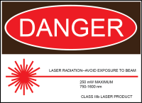
| Safety Class | 3B | |||
| Beam height | 0.95 | inches | ||
| Total package Size (L x W x H) | 3.75 x 4 x 2 | inches | ||
Laser Control Signals
 | The D2-100 laser module is factory aligned. It is not advised that the user attempts to re-align the laser in the field. If the laser becomes misaligned, please return the unit to the factory for realignment. |
Temperature Control Loops
The connections to the TECs and thermistors are made to an 8-pin Hirose connector (see table 2 for identity of connectors). The pin definitions are:
| Connector Location | Connector (Hirose Part Number) |
| D2-105 Bulkhead | HR25-7TR-8SA |
| Cable Connection to D2-105 | HR25-7TP-8P |
| Cable Connection to D2-100 | HR25-7TP-8S |
| D2-100 Bulkhead | HR25-7TR-8PA |
NOTE: Earlier models use a push-pull connector for the 8-pin connector to the DBR module. To remove take care to apply opposition forces with the thumb and forefinger knuckles against the housing. Excessive force could displace the output beam and require realignment.
Laser Current (SMA)
Never connect or disconnect the D2-100 Laser to a laser controller that is energized. Always power down the laser controller completely before making connections to this laser.
Always make sure to make a snug connection between the D2-100 and the current-carrying SMA cable, and between the cable and the laser controller.
Current is provided to the DBR chip through an SMA connector. The central conductor of the SMA connects to the laser anode, and the shield connects to the laser cathode. This is a direct, unprotected connection to the DBR chip, so care must be taken to avoid ESD damage.