Table of Contents
Compact ICE/Heterodyne Agile Laser (HAL)
Model No. Compact ICE/Heterodyne Agile Laser (HAL)
Document Revision: 1
Document Last Updated on 2022/08/26 22:43
Please read Limited Warranty and General Warnings and Cautions prior to operating Compact ICE.
Links
Click here for the Compact ICE API.
Click here for the Compact ICE/HAL Webpage.
Click here for the Unsupported Compact ICE GUI
Description
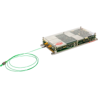 Fig. 1: The Compact ICE and HAL modules
The Compact ICE/Heterodyne Agile Laser (HAL) is an entire laser system built into a <550 cm3 package. It includes driving electronics for two lasers, a servo for Pound-Drever-Hall locking to atomic transition, an offset phase lock servo for locking a follower laser to the master, and temperature control electronics for the entire package. Also included are the two 780nm lasers, and Rb vapor cell required for locking.
Purchase Includes
- Compact ICE/HAL Modules
- Appropriate Power Cable
- Full or Half Cables for all Connections to the Module
Proper Usage
 | If this instrument is used in a manner not specified by the manufacturer in this manual or other relevant literature, protection provided by the instrument may be impaired. |
List of Symbols
 | Warning. Pay special attention to procedures and notes. If procedure is not followed carefully, damage to Compact ICE or devices connected to it may occur. |
 | Potential for electrical shock hazard. |
Specifications
| Performance1) | ||||
| Parameter | Min. | Typ. | Max. | Unit |
| Optical Power Output | 5 | 6 | 12 | mW |
| Center Wavelength | 780.241 | nm | ||
| Laser Linewidth | 450 | 650 | kHz | |
| Follower Laser Frequency Tuning Range | ±6.8 | GHz | ||
| Polarization Extinction Ratio | 20 | dB | ||
| System Operating Temperature Range | 25 | 40 | °C | |
| HAL Optics Package TEC Operating Current | 1080 | mA | ||
| Rb Gas Cell Operating Temperature | 40 | 46 | 48 | °C |
| Gas Cell Heater Current | 150 | 220 | 350 | mA |
| Laser Temperature | 15 | 25 | 35 | °C |
| Laser TEC Current | 15 | 100 | mA | |
| SOA Injection Current | 1080 | mA | ||
| SOA TEC current | 1000 | mA | ||
| Laser Injection Current | ||||
| Master Laser | 90 | 150 | mA | |
| Follower Laser | 130 | 150 | mA | |
| Relative Intensity Noise | ||||
| @ 10 Hz | -120 | -110 | dBc/Hz | |
| @ 100 Hz | -130 | -120 | dBc/Hz | |
| @ 1000 Hz | -140 | -125 | dBc/Hz | |
| @ 10000 Hz | -145 | -135 | dBc/Hz | |
| Follower Laser Offset Frequency Tuning Time | ||||
| Frequency Tuning <1GHz | 5 | 10 | µs | |
| Frequency Tuning >1GHz | 40 | 100 | µs | |
| Fractional Frequency Instability | ||||
| @ 1 s | 3E-12 | 6E-12 | ||
| @ 10 s | 8E-12 | 4E-11 | ||
| @ 100 s | 1E-11 | 8E-11 | ||
| @ 1000 s | 3E-11 | 2E-10 | ||
Physical/Electrical Connections
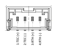
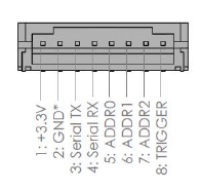
Compact ICE comes with two SMA current source connectors for external SOA, three SMP connectors for monitoring the external reference, beatnote, and laser modulation respectively, one 4 pin SOA TEC connector, a 5 pin power entry, and a choice between a USB-B mini connector, or an 8 pin serial TTL I/O connector for communication through the Compact ICE API. There are several other connectors listed in (figure 2), but none of them are user facing.
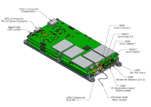 Fig. 2: Diagram of the Compact ICE showing connections
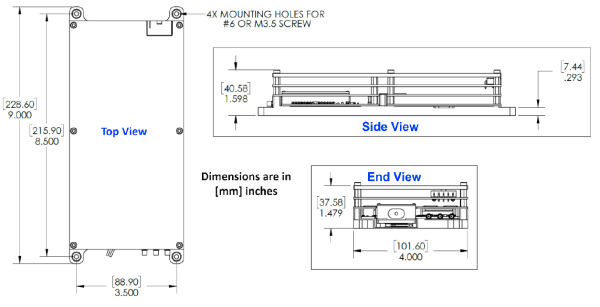
The baseplate comes with four size #6/M3.5 through-hole connectors for bolting down the Compact ICE. There is one optical fiber (PM FC/APC) output for the light from the follower laser.
Interface Connections
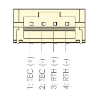
As some cables provided with the purchase of the Compact ICE are left as pigtails for user modification, the pinouts for various connections to the Compact ICE are given in this section. All cable diagrams are shown as if looking into the connector from the wire end.
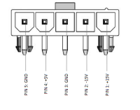 Fig. 4: Power Entry Connector.
You may also purchase more cables separately from Vescent.
Operating Compact ICE
GUI Disclaimer
This section of the Manual discusses operation of Compact ICE and uses screenshots of the Vescent provided GUI. However, it is worth noting that the GUI is not supported by Vescent, and is used only for demonstrational purposes. While the GUI is capable of performing many of the operations needed to use Compact ICE, only the API commands are fully capable of all Compact ICE functions. As such, it is recommended to not use the GUI outside of basic system tests, and to use the API commands instead.
Sending Commands
To send commands to Compact ICE through the serial USB-B Mini connector, we recommended using a terminal emulator such as Tera Term or PuTTy. The Baud Rate for Compact ICE must be set to 115200, and to receive replies from the commands it is always necessary to first send the #shadowUSART true command. More information about sending commands can be found on the API Commands page.
Connecting to the GUI
While use of the GUI is not recommended for data acquisition or critical operations, it can be a helpful tool for familiarizing oneself with the system and for experimental set up. To connect to the GUI, launch the application from the ICE Control folder on your desktop. A terminal window will open, and it may take a few minutes for the GUI to open. Once the GUI is open, select the appropriate COM port from the dropdown menu at the top, and press “Connect”. You will know you are connected if the numbers on the side bar corresponding to the installed cards light up.
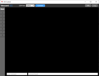 Fig. 8: The Compact ICE GUI home screen before connecting to a device.
API commands can also be sent through the field on the bottom of the GUI which reads “Enter Command”. If entering commands in this way, it may be necessary to refresh the GUI page by navigating to a different tab, and then back to see updates.
Powering On Compact ICE
After connecting the power supply to Compact ICE and turning it on, the “power” LED next to the connector will either turn, or begin flashing green. If a solid green light is present, this indicates that Compact ICE is powered on and ready to receive commands. If the light is flashing, Compact ICE is receiving power, but is not yet powered on and must be activated using the #PowerOn API command. The setting which controls whether Compact ICE boots immediately (Auto Turn On) can be configured via the #AutoPower <True/False> serial command, where <> denotes an argument and should not be included in the actual command . #AutoPower True will cause Compact ICE to boot immediately after receiving power from the power supply, giving the solid green light upon activation.
If using the GUI, it is necessary to turn Compact ICE on with the “Turn Power On” button that appears next to the “Connect” button after connecting. This particular API command cannot be sent through the GUI to turn Compact ICE on.
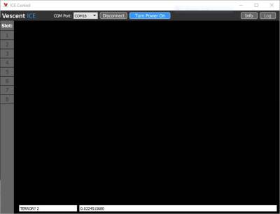 Fig. 9: The "Turn Power On" button is located next to the "Connect" button on the GUI.
General Commands/Navigation
Compact ICE comes with 5 separate boards each with their own set of commands, and a master board which handles general commands and navigation between the boards. When Compact ICE initially boots, it is necessary to first switch to the board you wish to send commands to. This can be done with the #slave <#> command, where '<#>' should be replaced with the number of the board you wish to communicate with.
For instance, sending #slave 3 will tell Compact ICE that you wish to communicate with the Offset Peak Lock board. Any board can be accessed from any other board by sending the appropriate #slave <#> command.
Temperature Control
After powering up Compact ICE and setting up the either the terminal or the GUI for sending commands, the first thing to do is temperature control all components of the system. Temperature controls are found on board 4, and there are 5 channels which can be controlled. Channel 2 controls the temperature of the HAL package (the case), Channel 3 controls the temperature of the Master Laser, Channel 4 controls the temperature of the Follower Laser, and Channel 5 controls the temperature of the Vapor Cell with the atomic reference. Channel 1 is left open for control of an external SOA through the SOA TEC connector.
The temperatures of all components are preset on shipment. In case the temperature drifts, it is possible to set the temperature of each channel with the TEMPSET <ch> <temp> command, where “<ch>” is the channel you wish to set the temperature of, and <temp> is a floating point temperature. To check the temperature of a channel, use the TEMPSET? <ch> command. Always check the temperature setpoint of a channel before turning it on. To enable the temperature servo on a channel, send the SERVO <ch> <ON/OFF> command. Do this for all channels after checking their setpoint temperature. It is imperative that the temperature servos be enabled before current is sent to the lasers. The TERROR? <ch> command can be used to monitor the progress of the temperature servo. It will display the difference between the setpoint temperature and the measured actual temperature of the channel in mK. This value reaches a maximum at 0.264mK and a minimum at -0.261. Outside of this range, it will only display the appropriate maximum or minimum value.
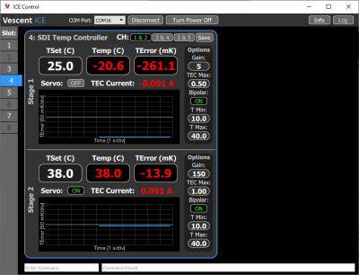 Fig. 10: A GUI representation of the Temperature Control Board with a plot of TERROR showing Ch 2 temperature stabilized and Ch 1 off.
The temperature of the lasers should always be between 15°C and 30°C. Damage to the lasers may occur if their temperature is set outside of this range.
To temperature control Compact ICE through the GUI, navigate to slot 4 by clicking on it in the menu bar on the left-hand side of the screen. The temperature channel can be selected with the buttons at the top of the screen labeled “CH” (1 & 2 | 3 & 4 | 3 & 5), and values can be entered directly into any field with white text. To Enable the servo, press the “Servo On/Off” button. Minimum temperature, maximum temperature, and gain can be adjusted through the vertical “Options” bar on the right.
Enabling Lasers
The two lasers inside the HAL packaging can be enabled either through board 7, or separately through boards 1 and 3 respectively. Once the temperatures of both lasers are stabilized, navigate to board 7 and check the current limits and current setpoints of each laser using the CURRLIM? <ch> and CURRSET? <ch> commands respectively, where “<ch>” is the channel you wish to check. It is recommended to keep the laser current limit at 135mA for both lasers. Once the limits and setpoints are set, the lasers can be enabled using the LASER <ch> ON command. Lasers can be disabled using the LASER <ch> OFF command.
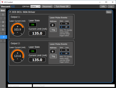 Fig. 11: A GUI representation of the Laser Enable Board.
These actions can also be performed through the GUI. As with the Temperature Control board, any field with white text can have values entered directly. The current limit can be set through the field below “Current Limit (mA)”, and the current supplied to the laser can either be selected by dragging the orange bar around the dial, or by typing a value directly into the field in the center. Note that, when dragging the bar, the value does not update until the bar has been released. These values may be slightly changed by the digitization scheme when entered.
Locking to the Atomic Reference
Navigate to the Peak Lock Board in slot 1. If the master laser has not yet been enabled, do so now by checking the current limit and current setpoint of the laser using CURRLIM? and CURRSET? respectively. Then enable the laser with the LASER ON command. Once the laser is enabled, turn on the ramp with the RAMPRUN ON command and look for spectroscopy. If your ramp sweep range is too low, it can be changed with RAMPSWP <V> where the ramp will sweep from -“<V>” to +“<V>”. To find the transition, change either the temperature of the laser, the current being delivered to the laser, or the servo offset. Temperature will give you the largest range of control and is best used for locating the transition. Servo offset gives the finest control, and is best used for lining up the particular transition you wish to lock to. Once the transition is lined up, the servo can be enabled using SERVO ON. On the GUI, the servo will lock to whichever transition is centered on the vertical line in the middle of the plot.
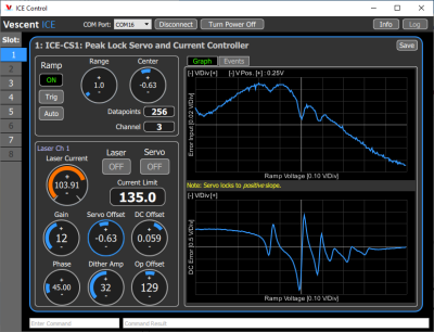 Fig. 12: A GUI representation of the Peak Lock Board.
If the servo doesn't lock, it might be because of your gain settings. To change those, use the GAIN <#> command. For more information on locking Compact ICE through the GUI, follow this guide which was written for ICE, but is the same for Compact ICE.
Offset Phase Locking
Navigate to the Offset Phase Lock Board in slot 3. If the follower laser has not yet been enabled, do so now by checking the current limit and current setpoint of the laser using CURRLIM? and CURRSET? respectively. Then enable the laser with the LASER ON command. Once the laser is enabled, turn on the ramp with the RAMPRUN ON command. The beat note input signal to the Offset Phase Lock Board is divided down by a factor of N (8, 16, 32, or 64) which can be checked and set using N? and N <#> respectively, where <#> must be a valid value of N. To get an offset phase lock, it is necessary to find the “house signal” (see figure 13). This can be done by adjusting the temperature of the laser, the current supplied to the laser, or by adjusting the servo offset. As with the Peak Lock board, the Temperature gives the largest range of control, and is best for finding the house signal, while the servo offset gives the finest control and is best for centering the house signal. The servo will lock to the positive slope of the house signal. If you would like to change it to lock to the other slope, you can invert the house signal with the INVERT ON or INVERT OFF commands. To enable the servo, use the SERVO ON command.
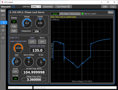 Fig. 13: A GUI representation of the Offset Phase Lock Board showing the "House Signal".
Once the servo is locked, it is possible to jump the frequency offset of the follower laser by changing the internal reference frequency. This can be done with the INTFREQ <freq> command, where <freq> is a floating point frequency offset between 1MHz and 250Mhz multiplied by the value of N. For instance, if the internal frequency is set to 200 MHz, and N is set to 16, the follower laser will have a frequency offset of 3.2GHz from the master laser. Operation of the Offset Phase Lock GUI is very similar to that of the Peak Lock board, with a few minor exceptions. The feature you lock to will always be the one with the positive slope, so there is less of a need to line that feature up perfectly with the center of the plot. Additionally, the plot will show the error about zero instead of a value corresponding to the locked feature.

