This is an old revision of the document!
Table of Contents
LS-105 2-D EO Laser Scanner Driver and LS-15-3005 Scanner Prototype Manual
Introduction
Please read Limited Warranty and General Warnings and Cautions prior to operating the D2-160. All specifications subject to change without notice.
Please be aware that the beam steerer and driver are still in the prototype stage. Please contact Vescent Photonics with any questions or concerns. If any glitches or malfunctions are noticed please contact Vescent Photonics. Please let us know if you have any suggestions for improving the functionality and/or capability of our scanner. We welcome your suggestions.
Vescent Photonics
14998 W. 6th Ave, Suite 700
Golden, CO 80401
Tel: 303-296-6766
Fax: 303-296-6783
General Warnings and Cautions
The following general warnings and cautions are applicable to this instrument.
WARNING This instrument is intended for use by qualified personnel who recognize shock hazards or laser hazards and are familiar with safety precautions required to avoid possible injury. Read the instruction manual thoroughly before using to become familiar with the instrument’s operation and capabilities.
CAUTION There are no serviceable parts inside the instrument. Work performed by persons not authorized by Vescent Photonics may void the warranty.
CAUTION Although ESD protection is designed into the instrument, operation in a static-fee work area is recommended.
WARNING To avoid electrical shock hazard, connect the instrument to properly earth-grounded, 3-prong receptacles only. Failure to observe this precaution can result in severe injury or death.
WARNING Do not clean outside surfaces of any Vescent Photonics products with solvents such as acetone. Front panels on electronics modules may be cleaned with a mild soap and water solution. Do not clean optics modules.
WARNING The user should NEVER disconnect the control cable from the scanner or driver while power is applied (“hot swapping”). Since the devices does not have internal pull-downs to ground, any voltage left on the device could permanently damage it, causing reduced throughput, highly degraded beam quality, and large in-plane scattering.
Limited Warranty
Vescent Photonics warrants this product to be free from defects in materials and workmanship for a period of one year from the date of shipment. If this product proves defective during the applicable warranty period, Vescent Photonics, at its option, either will repair the defective product without charge or will provide a replacement in exchange for the defective product. The customer must notify Vescent of the defective product within the warranty period and prior to product return. The customer will be responsible for packaging and shipping the defective product back to Vescent Photonics, with shipping charges prepaid. Vescent Photonics shall not be obligated to furnish service under this warranty from damage caused by service or repair attempts made without authorization by Vescent Photonics; from damage caused by operation of equipment outside of its specified range as stated in either the product specifications or operators manual; from damage due to improper connection to other equipment or power supplies. This warranty is in lieu of all other warranties including any implied warranty concerning the suitability or fitness of the product for a particular use. Vescent Photonics shall only be liable for the cost of repairs or replacement of the defective product within the warranty period. Vescent Photonics shall not be liable for any damages to persons or property resulting from the use of the product or caused by the defect or failure of this product. Vescent Photonics' liability is expressly limited to the warranty set out above. By accepting delivery of this product, the purchaser expressly agrees to the terms of this limited warranty.
Operating Parameters
Absolute Maximum Ratings Note: All modules designed to be operated in laboratory environment
| Parameter | Rating |
| Environmental Temperature | >15°C and <30°C |
| Environmental Humidity | <80% |
| Environmental Dew Points | <20°C |
Terminology
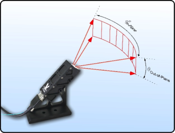
The LS-105 is a miniature electronics module designed to control an LC-waveguide electro-optic laser scanner. The electro-optic laser scanner is referred to as a Steerable-Electro-Evanescent-Optical-Refractor or SEEOR for short. The LS-105 provides a high voltage square wave of controllable amplitude to the three SEEOR electrodes (Steer Left, Steer Right, and Steer Down) for controllably steering the laser beam. The “horizontal” and “vertical” directions are as defined as shown in figure 2. The LS-105 also provides temperature control to keep the SEEOR at a uniform temperature.
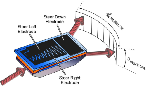 Fig. 2: A cartoon depiction of a SEEOR. The “horizontal” direction is defined as in the plane of the LC-waveguide. The “vertical” direction is defined as out of the plane of the waveguide. There are two horizontal steering electrodes and one vertical steering electrode.
With the LS-105 the amplitude of the square wave for each electrode is controllably adjustable from a minimum value, herein referred to as the Freedericksz voltage, to a maximum value of approximately 100Vrms. This is controlled via two analog input voltages via front panel BNC connectors, one for horizontal and one for vertical. The LS-105 provides an internal 5 kHz square wave, which may be monitored via a back panel SMA connection. An external square wave signal may also be applied via a back panel SMA connection. If an external square wave signal is applied, the LS-105 will detect this signal and override the internal square wave.
Specifications
| Parameter | Value | Comment |
| Number of HV Outputs | 3 | Two for horizontal electrodes and one for vertical. |
| Maximum HV | 100 Vrms | The user may input an analog control signal up to 11 V which will provide a Vrms of 110V but the specifications are not guaranteed for operation above 100 Vrms. |
| Maximum short burst HV current | 150 mA | For timescales <20 μs. |
| Maximum DC HV current | 6 mA | |
| HV Output Impedance | 1 kΩ | |
| Clock Out Voltage | 3.3V | |
| Vertical Analog Control Voltage Input | 0-10 VDC | Zero volts input is no deflection and 10 V is maximum deflection. |
| Horizontal Analog Control Voltage Input | -10 V to +10 VDC | -10 V steers all the way to the left, 0 V is centered, and +10 V steers all the way to the right. |
| Input Impedance for Analog Control Signals | 1 MΩ | |
| Clock Input Acceptable Frequency Range | 500 Hz to 10 kHz | At frequencies above 10 kHz the device will not operate to specification. A ÷2 circuit is employed for the external clock input in order to insure a symmetric signal is applied to the LC material. |
| Clock Input Acceptable Voltage Range | 3.3 V | 3.3 V is ideal. A 0 to 5 V TTL square wave will work; it is internally clamped to 3.3 V. |
| Internal Square Wave Frequency | 5 kHz | |
| Required Thermister Resistance | 10 kΩ | |
| Required TEC Resistance | ≥2 Ω | |
| Maximum TEC Current | 200 mA | |
| Power Input | 5V, 500 mA |
Operation
The LS-105 is shipped with a 5 V power supply and a cable for connection to the SEEOR, as shown in figure 3. If you purchased a chip level SEEOR the cable will have a connector on one end and clip-connectors on the other end. If you purchased a fiber-coupled SEEOR the cable will be connectorized at both ends.
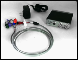 Fig. 3: The LS-105, power supply, and connection cable. The figure above shows a cable for connecting to a chip-level SEEOR. For a fiber packaged device, the cable will have connectors on both ends.
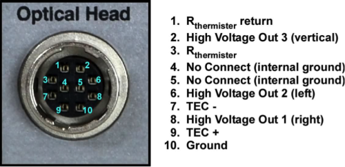
The cable plugs into the LS-105 with a push connector (female bulkhed connector: Hirose HR10A-10R-10SB; male cable end: Hirose HR10A-10P-10P). To remove the cable simply pull from the metal housing on the end of the connector. The connector pin-out is shown in figure 4. The clip leads are labeled appropriately.
Prototype EO Scanner Optical Head
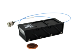
The 1.5 µm LS-15-3005-FC/PC is a prototype 2D electro-optical beam steerer. It requires the prototype EO scanner driver for proper operation, which was also included in the shipment. The scanner is packaged with a PM fiber pigtail (see figure 1) with an FC/PC connector. This is an engineering package and not intended for field use. Its input must be linearly polarized light with the polarization axis parallel to the FC key.
Connections and Controls
WARNING The user should NEVER disconnect the control cable from the scanner or driver while power is applied (“hot swapping”). Since the devices does not have internal pull-downs to ground, any voltage left on the device could permanently damage it, causing reduced throughput, highly degraded beam quality, and large in-plane scattering.
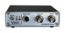
With the power switch in the OFF or down position (see figure 5) connect the power supply to the wall plug and to the LS-105 back panel (see figure 6). Use the provided cable to connect the LS-105 driver to the SEEOR unit. The unit is now ready to be powered on. The driver provides up to 110 V to the beam steerer. Please operate safely. Please allow 1 to 2 minutes for the SEEOR to temperature stabilize. Now the beam steerer is ready for steering. Connect your voltage source to the front panel BNC marked Horizontal and Vertical. A positive voltage at the “Horizontal” input will steer one way and a negative voltage will steer the other way. DO NOT EXCEED ± 10 V. Input impedance is 1 MΩ. For the “Vertical Scanning” input, use a positive voltage only.
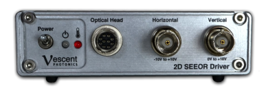 Fig. 5: LS-105 front panel
Front Panel Controls (from left to right)
| Power Switch | This turns the unit on. Up is on and down is off. |
| Power LED | This is on when the unit is on. |
| Temperature LED | This LED turns green when the temperature is stabilized. |
| Optical Head | High Voltage and temperature control output connector. |
| Horizontal | User can input the external signal. Maximum voltage should not exceed ±10 V. Input impedance is 1 M Ω. This input will steer the beam horizontally. |
| Vertical | User can input the external signal. Maximum voltage should be held within 0 to +10 V. Input impedance is 1 MΩ. This input will steer the beam vertically. |
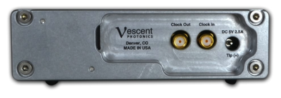 Fig. 6: LS-105 rear panel
Back panel Controls (from left to right)
| Polarity Clock Out | This outputs the clock frequency. The driver outputs an AM square wave to drive the beam steerer. As the square wave transitions polarity, there may be a minute change in the scan angle. If the user’s application is sensitive to this change the clock out provides a means to synchronize to this. |
| Polarity Clock In | If the user does not connect a clock input, the driver will use its internal clock that is set to 5 KHz. If the user inputs the clock signal, the internal clock will be disabled automatically and the external clock will be used. A ÷2 circuit is applied to the external clock input to ensure a symmetric waveform is applied to the LC material. |
| Power In | Power the driver with the AC adapter that is included with the package. |
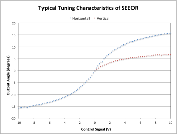
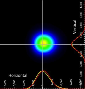
A typical angle tuning curve for a SEEOR is shown in the figure. And typical output beam quality is shown next to it.
Advanced Settings
Background on Driving LC Devices
When designing LC-drive electronics there are two important inherent properties. First, for a typical nematic LC, the EO response is via an induced dipole interaction. This means that the LC-molecules respond to the magnitude of the applied electric field but not the sign. Second, it is necessary that the time-averaged voltage across an LC optic is “DC-balanced” to have zero or minimal offset. This can be critical for both the operation and lifetime of the device. Prolonged time-averaged DC offsets will drive ion-migration inside the LC material, which can be deleterious for both the short-term performance and ultimately the lifetime of the device. On short timescales ion-migration will create a shielding field to cancel the applied voltage, which will cause the LC molecules to “relax” or “sag.” Precision applications can be sensitive to this sag even during short timescales. On long timescales ion-migration can result in the build up of permanent charge layers within the LC, thereby causing a “burn-in” which may forever degrade the operation of the device. The LC-drive electronics must account for both the “induced dipole” response and the “DC-balance” constraint.
An optimum voltage waveform that satisfies both of these LC requirements is a high quality square wave with no DC offset. Since the LC material only responds to the magnitude of the electric field and not the sign, by rapidly switching the voltage polarity the LC material will see the same E-field magnitude and simultaneously the need for DC balance will be satisfied. While in principle the square wave provides the ideal waveform, for anyone who has ever worked with square waves they will know that a high quality square wave is easier said than done. This is especially true when driving capacitive loads such as LC cells. Furthermore, high-quality square waves are extremely difficult if one requires higher voltage, such as required for high-speed LC-device driving such as LC waveguides.
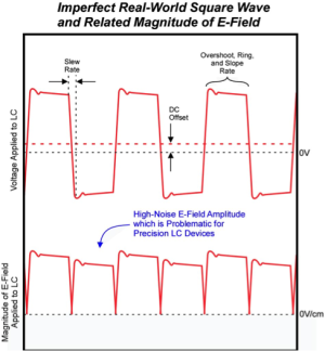
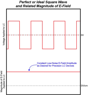 Fig. 9: Left) Drawing of a typical square wave as provided by common amplifiers. Slew rate, DC offset, overshoot, and ripple all result in a non-constant E-field magnitude. Since it is the E-field magnitude that the LC responds to this can be problematic. Right) Drawing of an ideal square wave and its related constant E-field magnitude. The goal of a proper LC-driver is to get as close to this ideal as possible.
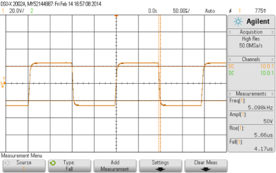
Common problems with square waves are illustrated on the left of figure 9. Typically, the square wave is generated via amplification of a low voltage clock from a function generator or other clock source. Frequently, amplifiers are susceptible to several common problems: offsets (often frequency dependent which hampers trimming), limited slew rates, limited settling times (can cause overshoot and ringing), and limited current output. As shown on the left of figure 9, all of these problems can have dramatic impacts on the magnitude of the electric field, i.e. what the LC responds to. For high-speed LC devices, the slew rate required to minimize any transient LC response during the polarity switch can be >100 Volts/ms, which is beyond the capabilities of most amplifiers when driving a capacitive load. The right hand side of figure 9 shows an ideal square wave and its associated constant E-field magnitude. figure 10 plots an example waveform from an LS-105. The LC-105 is designed to have an optimized waveform for driving the SEEOR capacitive load.
SEEOR: An Asymmetric LC Device
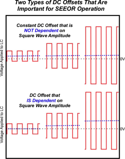
For conventional LC devices such as displays, the electronics are constructed to keep the DC offset minimized over all operational square wave voltages. In the SEEOR, the internal construction is inherently asymmetric. This asymmetry can lead to polarity dependent voltage drops across the LC layer that are a function of square wave amplitude. This effect can lead to a splitting or “twinning” of the scanned laser spot, i.e., the scan angle will change slightly as the square wave polarity is switched. Applying a voltage-dependent DC offset to the square wave can compensate this. A cartoon of both a constant and voltage-dependent DC offset is shown in Figure 9.
Internal Factory-Set Trim Pots
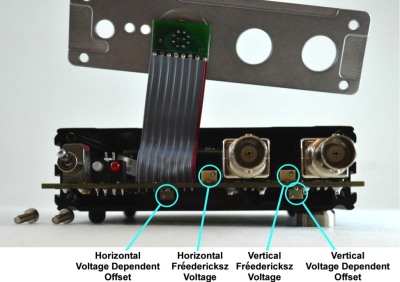
There are a number of internal trim pots that are factory set. These are typically set for a specific scanner. If you are using the same driver with different scanners it is possible that these could be re-optimized for a new scanner. Under normal operation, these pots do not need to be user adjusted. By unscrewing the four hex-bolts and the two BNC washers, the front panel may be folded up to allow access to four of the internal trim pots, as shown in Figure 10. From here, the user may adjust the magnitude and sign of the voltage dependent offsets. If the scanner has more than acceptable twinning or splitting of the scanned beam, especially at maximum deflection, then it may be beneficial to adjust the magnitude of the voltage dependent offset. Note, this trim pot can provide both a positive and negative offset. These trim pots are shown in Figure 10. With the scanner attached and this device running (please be careful of high voltage) set the LS-105 for maximum deflection (10 V). If the spot is twinning then these trim pots can be adjusted to minimize the twinning. Also shown in Figure 10 are the trim pots for setting the Freedericksz voltages. A typical LC does not respond until the applied voltage hits a threshold. This threshold is called the Freedericksz voltage. There is no point in applying voltages below this threshold. These trim pots set the absolute minimum square wave amplitude.
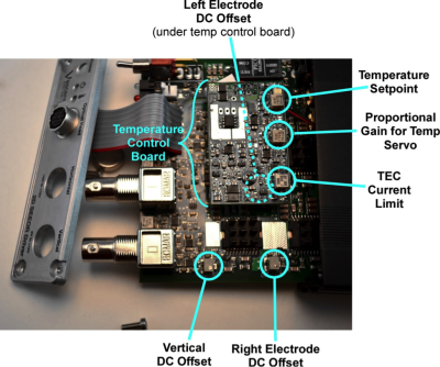
There is another set of trim pots that are only accessible by sliding the electronics out of the housing. Note, when doing this make sure to unplug the two-pin Molex connector that powers the cooling fan. Inside the LS-105 there are two electronics boards. The smaller board is for temperature control. This provides a PID temperature loop. The I and D poles are factory set for typical SEEOR thermal plants. The P pole is fine tuned by the trim pot. There are also trim pots for both the set temperature and the TEC current limit. These are factory set and should not be altered without first contacting Vescent. The temperature is set to stabilize the SEEOR to 30 °C. The TEC current limit is set to 200 mA. There is also a trim plot to minimize the constant DC offset for each of the three SEEOR electrodes, as shown in Figure 11. One of these is underneath the temperature control board. The temperature control board can be removed by detaching the mounting screw and simply pulling it up. The LS-105 will run just fine without the temperature control board. With the input BNCs grounded the high-voltage output may be measured with a voltmeter. If the voltmeter is set to DC ,this can be a good way to measure the constant DC offset. These trim pots may be adjusted to minimize the offset.

