
Table of Contents
SLICE-QTC Four-Channel Temperature Controller
Model No. SLICE-QT and SLICE-QTC
Document Revision: 1
Document Last Updated on 2023/08/11 14:53
Please read Limited Warranty and General Warnings and Cautions prior to operating the SLICE-QTC.
Links
Click here for the SLICE-QTC Quick Start Guide.
Click here for the SLICE-QTC API.
Click here for the Ziegler-Nichols loop tuning instructions.
Click here for the SLICE-QTC web page.
Click here for the Github page for SLICE-QTC GUI
Click here for the Github page for SLICE-QTC firmware revisions
Please check back for added functionality. Contact sales [at] vescent [dot] com for questions and corrections, or to request added functionality.
Description
The SLICE-QTC is a high-precision temperature controller (see figure 1). It will control up to four thermal plants with sub-millikelvin precision.
Purchase Includes
- SLICE-QTC Temperature Control Unit
- AC power cord with appropriate wall plug for you location (if known)
- Four single-ended 6-ft control cables1)
- Final Test Documentation
Absolute Maximum Ratings and Power Input
Note: All modules designed to be operated in a laboratory environment.
The SLICE-QTC will accept input line voltages within the ranges shown in table 2.
| Parameter | Value | Units |
| Input Line Voltage | 100-240 | VAC |
| Frequency | 50-60 | Hz |
| Phase | 1 phase | |
| User-serviceable fuse2) | T 2.0 A L 250V | |
Proper Usage
 | If this instrument is used in a manner not specified by the manufacturer in this manual or other relevant literature, protection provided by the instrument may be impaired. |
| Successful implementation of the SLICE-QTC depends critically on the design of the whole system: controller, transducer, plant, and sensor. |
Tips for Successful Temperature Regulation
- The transducer, plant, and sensor must all be in good thermal contact. Use thermal paste or epoxy to avoid air gaps between a TEC or heater and the body of the plant as well as to secure the thermistor to the plant.
- Know the electrical limits of of your transducer and set the limits of the SLICE-QTC accordingly. Each channel can provide up to 6 A or 20 W of power with a maximum compliance voltage up to ~18 V. Choose transducers that work within these limits. Using the current, power, and/or voltage ratings of your transducer to calculate loads on individual channels and set limits appropriately in the CH X > Settings > Load Limits window.
- Maintain proper shielding of the control cable, but avoid ground loops between the SLICE-QTC and the plant. In most cases this means extending the foil shield in the cable to as close as possible to the plant without electrically connecting the SLICE-QTC to the plant.
Never connect either of the TEC leads on a plant, or the SLICE-QTC to ground. This configuration is very likely to cause severe damage to the SLICE-QTC.
List of Symbols
| | Warning. Pay special attention to procedures and notes. If procedure is not followed carefully, damage to the SLICE-QTC or devices connected to it may occur. |
 | Potential for electrical shock hazard. |
Specifications
| Performance3) | |
| Parameter | Value |
| Channels | 4 |
| Loop Filter | PID, adjustable corners and proportional Gain |
| Control Range | -20 to +120°C 4) |
| Compatible Transducer | TEC or resistive heater |
| Compatible Sensor | NTC thermistor 5) |
| Temperature Stability | ±0.2 mK over 10 min6) |
| Precision | ±0.2 mK |
| Control Capacity | 40 W total7) 20 W max for a single channel |
| Current Capacity | 6 A per channel8) |
| Compliance Voltage | ≤18 V9) |
| Input & Output | |
| I/O Voltage Range | ±10 V |
| Triggering | TTL |
| Control Interface | |
| Control | Front-panel touch screen, GUI, Serial API |
| Connections | Host control: USB Type B |
Extendable Legs
The SLICE-QTC has four extendable legs (figure 2). Extending the front legs allows easy viewing from above (figure 1) and extending the rear legs (figure 3) allows easy viewing from below.


Front Panel
An image of the front panel is shown in figure 4. The functions and connections are as follows:
- Parameter input adjustment knobs
- Control signal inputs
- Signal monitor outputs
- Touch screen with view of CH 2 Details screen
- ∆T plotted as a function of time (blue line)
- System locked range (yellow dashed lines)

Rear Panel
An image of the rear panel is shown in figure 5. The functions and connections are as follows:
- Main On/Off power switch
- AC line power in10)
- User-serviceable fuse (T 2.0 A L 250V)
- Output trigger (BNC)
- Input trigger (BNC)
- USB port (Type B)

Interface Connections
Connections to the thermal plants are made from the rear panel. Four cables for this purpose are provided with the SLICE-QTC. Each has one end terminated with a CUI Inc. PDP-40 connector for connecting to the CUI Inc. CP-7240-ND connector on the SLICE-QTC. The other end is unterminated and is for connecting to your specific plant. The pin out for connecting the cable (Beldon 1502R 010500) to your specific plant is given in table 4.
| | Do not have servo loop engaged when connecting Servo Output to your plant. |
| | Use caution grounding the shield (drain) at the transducer end of the interface cable as ground loops may be formed, degrading performance. Consider floating the plant or not connecting the shield to the plant chassis. |
You may purchase more cables separately from Vescent Photonics. We do not recommend making cables, but if you do so, make sure the metal sleeve is well connected to the connector ground to provide proper shielding to the signal cables.
Operating the SLICE-QTC
Screen Navigation
The touch screen interface and the Host GUI operate in a substantially similar way, except touch is substituted for a click in the touch screen interface.
When presented with a given view, it is possible to select the functionality or edit the values in a field bordered in blue. When a particular field is actively being edited, its border will change to yellow. The Home Screen of the SLICE-QTC is shown in figure 6. From the Home screen, summary control over the four channels is possible, including setting Tset, initiating lock, or entering an individual channel's Detail screen.
In general, the status displayed in an editable field is the current status (not the result of touching the button). Touch the field to select a new value/status. For instance, in figure 6 all of the channels are in stand by. Touching the OFF button to initiate servo control over a plant will change this button to read ON (figure 17).
 Fig. 6: Home screen of SLICE-QTC
To navigate away from a menu, it is typically necessary to press the escape button found on that menu. However, certain drop downs without a escape button, such as those found in the Auto Tune process, can be closed by touching anywhere on the screen outside of the menu. In general, if the menu has a escape button on it, the escape button must be pressed to exit the menu.
Control Bar
On the left edge of the screen is the Control Bar. At any given time, these buttons will have the following effect.
Home Button
 Fig. 7: Home button
Returns to Home screen (figure 6).
Fig. 7: Home button
Returns to Home screen (figure 6).
Back Button
 Fig. 8: Back button
Returns to previous screen. Changes will be lost if not accepted before using the Back button.
Fig. 8: Back button
Returns to previous screen. Changes will be lost if not accepted before using the Back button.
Lock Button
 Fig. 9: Lock button (shown in unlocked mode)
Locks out further modification of parameters. Touch to lock or unlock parameter entry. It is still possible to engage the temperature control loops when system is locked, but it is not possible to change the set point temperature or loop parameters, etc.
Fig. 9: Lock button (shown in unlocked mode)
Locks out further modification of parameters. Touch to lock or unlock parameter entry. It is still possible to engage the temperature control loops when system is locked, but it is not possible to change the set point temperature or loop parameters, etc.
I/O Button
 Fig. 10: I/O button
Enters the screen for programming the front-panel I/O.
Fig. 10: I/O button
Enters the screen for programming the front-panel I/O.
System Settings Button
 Fig. 11: System settings button
Enters screen for system control settings (brightness, volume, etc.).
Fig. 11: System settings button
Enters screen for system control settings (brightness, volume, etc.).
Entering Values
In order to afford maximum resolution, the least significant digit will not necessarily change to precisely your target value and will be coerced to the nearest acceptable value, which is limited by the digitization scheme for the set point. For instance, you may select a set point temperature of 17.000°C, but the closest allowed digitized value may be 16.999°C.
In most instances, there are two methods for entering parameter values: the physical rotary knobs on the front panel and the pop-up keypad on the touch screen. When using the knobs to change the value of a parameter, changes take effect immediately. When using the keypad, changes do not take effect until the enter key is depressed.
Rotary Knobs
If you touch an editable field for a brief moment, a cursor will appear under one of the digits of the parameter value. By turning the right knob, it is possible to increase (cw) or decrease (ccw) the value of the underlined digit. Turning the left knob will change which digit is editable (cw to move to the right and ccw to move to the left).
Keypad
If you touch and hold an editable field such as the set point temperature, a numeric keypad will appear as seen in figure 12. You can enter in the full value of the desired parameter with this keypad.
 Fig. 12: Pop-up Keypad
The action initiated by each button is described below.
Escape

Clear

Delete

Enter

Home Screen
The Home screen summarizes the status of all four channels (figure 6). The data for each channel is arranged vertically. At a glance, for each channel, Tset, Tact, and ∆T can be read, as well as whether servo control is engaged. If the loop is engaged and ∆T is smaller than a user-defined range, the Error value field will be green, indicating a locked state. If ∆T is outside this user-defined range, this field will turn yellow.
Setting the Temperature
To set the temperature set point from the home screen, touch the Setpoint window for the desired channel (circled in red for CH 1 in figure 17). A long touch will cause a keypad to appear. Enter desired value and touch the accept button.
A short touch will highlight the Setpoint window in yellow (figure 18). Use rotary knobs to select digit to edit (left knob) and value for digit (right knob).
 Fig. 17: Select Temperature setpoint for CH 1

Enabling Feedback
Touch the OFF button at the bottom of the column for the desired channel. The button will turn white and read ON to indicate the SLICE-QTC is actively controlling the temperature for that channel. PID settings may still need to be input for the SLICE-QTC to servo plant temperature correctly. In figure 17 and figure 18 CH 1 is active and CHs 2-4 are inactive.
As the system approaches lock, it will display ∆T on a yellow background. When the system is locked (as defined by the user in the CH X > Settings > Limits screen) the Error window will display ∆T with a green background.
Channel Detail Screen
You can set how individual channels behave in the Channel Detail screen. To enter a Channel Detail screen from the Home screen, touch the CH button for the appropriate channel (figure 6). figure 21 shows the CH 1 Detail screen. From this screen, you can change Tset, and initiate temperature control as from the Home screen. You can also visually monitor the performance of the loop. When the lock is engaged, the graph in the lower right of the screen displays ∆T (Tact - Tset) on a rolling basis. The yellow dashed lines indicate the user-defined “lock range” (see figure 24). In figure 21, the lock range is set to ±3 mK. If ∆T is outside of this range, the Error field background will change from green to yellow.
- Change the speed of the rolling display: touch the
 button and select from 1 to 20 s/div.
 - Change the scale of the vertical axis: touch the
 button and select from 1 mK/div to 10 K/div.
 - Pause and restart the rolling screen: touch the
 button.
 - Turn on & off cursors on the graph: touch the
 button. It is possible to drag the cursors across the display of ∆T to measure an oscillation period. This function will be helpful when tuning the loop parameters to your plant.


Adjusting the Graph
To adjust the vertical range (∆T) of the graph, either touch the  button and select an option from the pop-up menu (figure 19), or turn the right rotary knob.
 Fig. 19: Menu to adjust y-axis on temperature plot
To adjust the time base (∆t) of the graph, either touch the  button and select an option from the pop-up menu (figure 20), or turn the left rotary knob.

Display of Transducer Current, Voltage, and Power
As shown in figure 21, the current being delivered to the transducer is displayed in the blue box on the right margin labeled Current [A]. If you touch the blue box, the box will rotate through displaying current through, voltage across, and power delivered to the transducer.
From this screen, you can also set the various parameters for how the loop will behave.
 Fig. 21: Initial view of CH 1 Detail screen
Setting Control Modes
Touch the Settings button in the top right of the window. The sub-menu shown in figure 22 will appear.

Channel Settings
PID Filter and Slew Rate Adjustment
PID Settings
 Fig. 23: Screen for adjusting PID parameters for individual channel
To set the PID loop filter parameters from the Home screen, select CH X > Settings > PID Params and the screen in figure 23 will appear. The parameters for the PID loop filter are set in this popup screen. These parameters control the closed-loop behavior of the feedback. Each of these parameters will need to be tuned specifically for your plant, either manually or with the Auto Tune feature. There are a number of methods to tune a loop. We recommend the Ziegler-Nichols method.13) Instructions on using this method can be found here. There is also an option to enable or disable each parameter in the loop filter.
Slew Rate Limit
For applications where the rate of change of the temperature of the plant needs to be controlled, it is possible to set an upper limit on the slew rate. This can also be done through the PID Params screen.
| Setpoint | °C | Sets the setpoint temperature of the plant. |
| Proportional | V/V | Sets the proportional gain of the loop filter. |
| Integral | sec | Sets the integral time constant of the loop filter. |
| Derivative | sec | Sets the derivative time constant of the loop filter. |
| Slew (Rate) | ºC/min | Sets the maximum slew rate for the plant temperature. |
 | If appropriate, make sure to turn the Slew Rate Limit off when changing use case! |
Maximum & Minimum Temperature, Lock Range
Set Maximum & Minimum Temperature
The maximum and minimum allowable temperatures (Tmax and Tmin) can be set as well as the range of ∆T where the system is considered to be locked. From a Channel Detail screen (figure 21), tap Settings > Temp Limits and the screen in figure 24 will appear. It is advised to set Tmin above the dew point temperature for your ambient conditions to avoid condensation on your plant surface. If the temperature of the plant exceeds the range set by Tmax and Tmin, the temperature will be displayed in a flashing red field.
Set Lock Range
In the view shown, the lock range has been defined to be ±3 mK. If -3 mK ≤ ∆T ≤ +3 mK, ∆T will be displayed on a green field. If outside this range, ∆T will be displayed on a yellow field. The graph in the bottom right of the Channel Detail screen plots ∆T vs. time. The dashed yellow lines on this plot represent the lock range limits as set in this screen.
 Fig. 24: Menu for setting absolute extrema and lock range
| Locked Range | ºC | Defines the nominal operating temperature range for the plant. When the actual temperature is within this window (±value), the temperature error will be displayed on a green background. When the error in the temperature is outside this window, the temperature error will be displayed on a yellow background. |
| Maximum Temp | ºC | Sets the maximum and minimum operating temperatures of the plant. The user will be prevented from adjusting the setpoint temperature to outside this range. If the actual temperature exceeds this range, the temperature will be displayed on a flashing red background. |
| Minimum Temp | ºC | |
| Shutdown Time | s | Sets the delay between when the temperature goes out of range and when the SLICE-QTC shuts the current off. |
| | If your plant is exposed to the atmosphere, use an abundance of caution in setting Tmin below the dew point for your ambient conditions! Water will condense on surfaces that are below the dew point temperature. |
Power Limits
The User can limit the control power available to individual channels. To adjust control capacity from the Home screen, select CH X > Settings > Load Limits and the screen shown in figure 25 will appear.

Transducer and Thermistor
To set the properties of the transducer (TEC or heater) and thermistor for an individual channel from the Home screen, touch CH X > Settings > Plant. The menu in figure 26 will appear. Select TEC/Bipolar (as seen) or select Heater/Unipolar by touching the TEC/Bipolar button to toggle between the two.
From this screen, it is also possible to set the polarity of the TEC. Touch Polarity Positive/Polarity Negative to toggle between the two states. The polarity is already set correctly to NEGATIVE for use with NTC thermistors.
The thermistor data has been configured at the factory for a typical NTC thermistor that is 10 kΩ at 25°C. Only NTC (Negative Thermal Coefficient) thermistors can be used. You can enter a new Beta value, reference temperature, and resistance value and the Steinhart-Hart constants will be calculated automatically or vice versa.
NOTE: The SLICE-QTC can achieve sub-millikelvin stabilities over a very wide set point temperature range. For most applications working near room temperature, an NTC thermistor with a nominal value of 10 kΩ at 25°C will work fine. For temperatures far from room temperature, best results will occur by choosing a thermistor that has a resistance of 10 kΩ at your desired set point temperature. The input bridge circuitry is configured to have maximum sensitivity at a 10-kΩ resistance.
 Fig. 26: Set Thermistor and Plant Information
| | WHEN USING A RESISTIVE HEATER, be sure to set the transducer type (CH X > Settings > Plant) to Heater/Monopolar. If set to TEC/Bipolar, attempts by the SLICE-QTC to actively cool your plant will result in a thermal runaway condition. |
Front-panel Inputs & Outputs
The front panel of the SLICE-QTC has two analog inputs (channels A & B) and two analog outputs (channels 1 & 2, not to be confused with the temperature control channels) available for use. The two analog outputs can be configured to output useful monitor signals, while the two analog inputs can be configured to provide additional functionality. A schematic of the input and output functionality is shown in figure 29, with the light blue boxes indicating the front panel I/O. The voltage range of the analog I/O on the SLICE-QTC is ±10 V.
To program the functionality of the front panel I/O, from any screen, touch the I/O icon on the left sidebar. You will be presented with the screen shown in figure 27.
 Fig. 27: Programming the front-panel I/O
Touch the blue-framed window to the right of the I/O channel you wish to program. Upon doing so, you will be presented with a pull-down menu of the various options available for that channel. For instance, if you select channel A input, you will be presented with the screen shown in figure 28. You can select the input to be any of the signals shown in table 7 for any of the four temperature-control channels.
 Fig. 28: Programming the input on Channel A Input
Each selected function for inputs and outputs will have settings that you can adjust, specific to the chosen functionality. To access these settings, select the Settings (“gear”) icon that is just to the right of the selection window. A pop-up window will be presented that displays the various settings that can be adjusted for that feature.

Input Channels A & B
External Set Point
In this mode, an external signal can be used to supply the set point temperature of the plant. The set point temperature is related to the input voltage (Vin) by: Set Point Temp [˚C] = Gain [˚C/V] x Vin + Offset[˚C]. Touch the Settings icon to the right of the channel selection to adjust the Gain and Offset. This mode comes with both an absolute, and relative option, which can be selected separately through the I/O menu.
External Temperature Input
This mode allows a bypass of the temperature read from a thermistor on a plant to use a temperature from a device that generates voltage as a function of temperature. The temperature is related to the input voltage (Vin) by: Temperature [°C] = Gain x Vin + Offset. Touch the Settings icon to the right of the channel selection to adjust the Gain and Offset.
External Error Input
This mode allows the temperature error to be derived from an external temperature transducer. In this mode, the thermistor and associated signal processing electronics are not used. The temperature error is related to the input voltage Vin by: Temperature Error [˚C] = Gain [˚C/V] x Vin + Offset [˚C]. Touch the Settings icon to the right of the channel selection to adjust the Gain and Offset.
Feedforward
This mode allows a feedforward signal to be summed into the output of the PID loop filter. The feedforward signal current is related to the input voltage Vin by: Feedforward Current [A] = Gain[A/V] x Vin + Offset[A]. Touch the Settings icon to the right of the channel selection to adjust the Gain and Offset.
Slow Servo Input
In some use cases, it is convenient to have the temperature set point automatically adjusted to keep another external parameter (which depends on temperature) at a certain value. For instance, the frequency of a laser might be controlled by adjusting the cavity length via a piezoelectric transducer (PZT). Over time, the cavity length may drift outside the range of the PZT, causing the laser to unlock. In this case, the laser cavity might have its temperature automatically adjusted so as to center the PZT voltage in the middle of its operating range.
When this mode is active, the input signal is compared with a set point voltage (settable by the user) to derive an error signal that is input to a single integrator loop filter. The output of the integrator automatically adjusts the the temperature set point to maintain the input voltage signal at set point voltage. When the slow servo is enabled for a channel, the temperature setpoint field for that channel on the home screen will be highlighted blue, as shown in (figure 30).
 Fig. 30: Slow Servo enabled on channel 1
The setpoint temperature of the slow servo channel can still be adjusted, by touching the Setpoint [°C] field. To adjust the slow servo settings, press and hold on the blue Setpoint [°C] Field. This will bring up the slow servo menu as shown in (figure 31).
 Fig. 31: Slow Servo menu showing adjustable parameters
This can be done either from the home screen or the single channel summary menu. Gain, polarity, and setpoint can also be adjusted from the I/O menu by pressing the “gear” icon next to the A or B input where the slow servo is enabled.
| Choice | Comment |
| Off | Value not read |
| External Set Point | Externally control the set point temperature |
| External Temp Input | Alternate input path for plant temperature |
| External Error Input | Alternate input path for error signal (bypasses wheatstone bridge) |
| Feed Forward | Sums input value with loop filter output. |
| Slow Servo Input | Input is routed through an integrator and then used to control the set point |
Output Channels 1 & 2
Similarly, you can program the output signals for the Output Channels 1 and 2. For each channel, the actual (measured) temperature, the temperature error, or the current output can be chosen as the output signal. For instance, if you select Channel 1 Output from figure 27 you will be presented with figure 32. You can choose any value from table 8 to be delivered to the Channel 1 Output output on the front panel. Touch the Settings icon to the right of the channel selection to adjust the Gain and Offset for these output signals as in figure 33. When porting the Temperature of a given loop to an Output, setting the Gain equal to 0.1 V/°C and the offset to 0 V will give a convenient 2 V output at 20°C.
 Fig. 32: Programming the output on Channel 1 Output
 Fig. 33: Adjusting the Gain & Offset of Channel 2 Output
When the SLICE-QTC is programmed to deliver data to an output port, the data that is being delivered will be indicated on the Channel Detail screen as seen in figure 34. The numeral 1 in the magenta circle in the upper right-hand corner of the Actual [°C] display field indicates that the temperature for CH 4 is being delivered to the front-panel I/O port ch 1.
 Fig. 34: CH 4 ∆T data is being delivered to front-panel I/O channel 1
| Choice | Comment |
| Off | No data delivered to output channel |
| Temperature | Actual temperature measured by thermistor |
| Temperature Error | Temperature error ∆T = Tact - Tset: Actual temperature minus set point temperature |
| Current Output | Current being delivered to specified temperature control channel |
Triggering
External control of the SLICE-QTC is accomplished via a TTL trigger.14) 0 to 0.8 V TTL is low and 2 to VCC is TTL high.
Trigger Out
The Trigger Out on the back panel of the SLICE-QTC can be forced to go high to alert an external device to a status change. To program the trigger, from any screen touch I/O > Trigger Out. You will be presented with the screen shown in figure 35. Select those events on the desired channels for which you want the trigger to go high. A logical OR is performed on the set of selected events to determine the state of the output trigger. In the example, the trigger will go high if the minimum temperature set for CH 1 is exceeded, the maximum temperature set for CH 2 is exceeded, the maximum slew rate set for CH 3 is exceeded, or when CH 4 reaches its set point temperature.

Trigger In
The Trigger Input on the back panel of the SLICE-QTC can be used to turn any of the four temperature control channels on or off. The trigger can be configured from the I/O menu, under “Trigger In”. Select the “Channels” field and choose which channels you want to be affected by the trigger. Applying 5V to Trigger Input will enable the servo for all selected channels, and applying 0V will disable them.
As of 2 August 2023 with up-to-date firmware, it is possible to invert the SLICE-QTC response to a trigger input. For instance, the SLICE-QTC can be programmed to either turn on or turn off a given channel when the input is trigger goes from low to high or vice versa.touch I/O > Trigger In and figure 36 will be displayed.
 Fig. 36: Programming the rear-panel trigger out
Auto tune cannot be run for a channel which is under trigger control. Attempting to run an auto tune on a channel with a trigger input enabled will bring up a dialogue: “External input not compatible with auto tune. Turn external input off and continue?”. Pressing OK will disable the trigger for that channel and begin the auto tune. Pressing “Cancel” will dismiss the dialogue, leaving the trigger enabled, and the auto tune will cancel. Additionally, a trigger cannot be enabled on a channel with an active auto tune being run.
Auto Tune
The auto tune feature of the SLICE-QTC allows the user to automatically find the PID temperature tuning parameters of their plant. It can be run from the single channel screen by pressing on the “Servo” button and choosing “Auto Tune”, then pressing “Start” from the “Next” drop down menu.
 Fig. 37: Auto tune menu showing a tune ready to start
Note that there is also an “Auto Tune” option under the “Settings” menu. However, this will display the results of the most recent completed auto tune and cannot be used to start an auto tune. Once the auto tune starts, it will progress through several stages, and the user will be updated on its progress through a loading bar.
 Fig. 38: An auto tune underway, showing the loading bar
Once the bar reaches 100%, the user is given the option to accept, review, or cancel the results.
 Fig. 39: A completed auto tune with the Accept/Review menu displayed
Accepting the tune will set the PID parameters of the temperature channel based on the calculated ultimate gain and period for the tuned plant. Reviewing the results will display a menu showing the PID parameters without setting them on the temperature channel.
 Fig. 40: The review menu for a completed auto tune
Canceling the result will exit the auto tune without setting the PID parameters on the temperature channel. If the results are canceled , they can still be seen in the “Settings” –> “Auto Tune” menu.
System Settings
Touching the System Settings button on the Control Bar (figure 11) will open the System Settings screen as seen in figure 41.

User Interface Appearance
From this screen, adjustments to the brightness of the screen and the volume of the audio feedback can be made.
Input Impedance
Change the input impedance of the two front-panel input ports. Select either 50 Ω or 1 MΩ.
SLICE-QTC Serial Number
The serial number (“S/N”) of the SLICE-QTC is displayed in the top right hand corner of the screen.
SLICE-QT Firmware
Current firmware versions are reported here.
From time to time, Vescent will upgrade the firmware for controlling the SLICE-QTC. The procedure to upgrade the firmware is given here.
Host GUI
If accessed through a PC Host GUI, the Settings screen (figure 42) also has the ability to assign the COM port for the device. If viewed through the GUI, there are no brightness or volume controls as these should be set on the PC directly.
 Fig. 42: User-programmable system settings from host GUI
Servo/Manual Modes
Under most circumstances, the system will control the current to the transducer in order to minimize temperature fluctuations of your thermal plant. From time to time, it may also be desirable for the user to directly control the current to the transducer. This is done in Manual mode (open-loop control). To toggle between Servo and Manual modes, touch Servo on the Channel Detail screen (figure 21). In Servo mode (closed-loop control), it is possible to adjust the set point temperature, but not the current. In Manual mode, it is possible to adjust the current, but not the set point temperature. Caution should be exercised when using Manual mode as it is possible to create a thermal runaway condition where the transducer heats or cools without being limited.
| | In Manual mode, it may be possible for a thermal runaway condition to exist. Use caution when using Manual mode. |
Using the Host GUI
It is possible to control the SLICE-QTC from a Windows®-based PC using a GUI. In order to use the GUI, you must first download the latest version, connect the PC to the SLICE-QTC, and assign a COM port to the SLICE-QTC. The following describes the steps involved.
- Download and store the latest GUI executable from the Vescent FTP site (or request copy of executable GUI from sales [at] vescent [dot] com).
- Connect the SLICE-QTC to the PC using a USB type B cable.
- Turn on the SLICE-QTC.
- On the PC, double click on the SLICE-QTC GUI to start the GUI.
- On your PC, go to Start > Control Panel > Device Manager > Ports
- Identify which COM Port is labeled “STMicroelectronics Virtual COM Port (COMXX)” or similar. Note the value of XX.
- On the SLICE-QTC GUI, click on the Settings icon
 to get to the window shown in figure 43.
 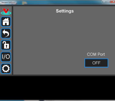 Fig. 43: Settings screen when viewed by GUI
 - Click on the OFF button below COM Port. You should see a menu similar to the one shown figure 44. NOTE: The COM port numbers may differ from those shown below.
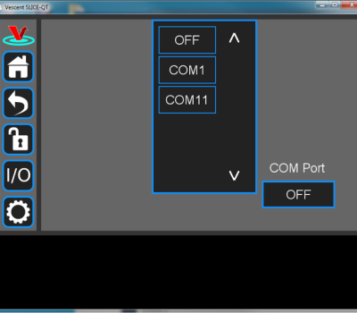 Fig. 44: COM port selection
 - Select the COM port identified in the step above (usually the last COM port in the list; COM11 in this example). The window in figure 45 should appear if the connection is successful.
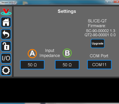 Fig. 45: Ready to upgrade


The GUI should now actively control the SLICE-QTC. You should only have to do the above steps once from a given PC. After assigning the COM port, the system will recognize the device in the future (unless you reassign the COM port to another device).
Firmware Update
From time to time, Vescent will upgrade the firmware for controlling the SLICE-QTC. The procedure to upgrade the firmware is given here and a video tutorial can be found here.
Serial API
It is possible to control the SLICE-QTC through serial commands. Most functions of the SLICE-QTC which can be performed through the GUI are also available through the serial API. These commands can be sent either through a terminal emulator such as PuTTy or Tera Term, or via a python script as shown in this application note. Click here to access the SLICE-QTC API.
Upgrading the SLICE-QTC firmware is not always necessary to use the Serial API. Check your installed firmware version in the settings menu against the most recent firmware version given here.
Please contact sales [at] vescent [dot] com for information.
Maintenance
There are no user-serviceable parts inside this instrument. Refer all repairs to the manufacturer. Work performed by persons not authorized by Vescent Photonics may void the warranty.