
slice:dhv
Table of Contents
SLICE-DHV Dual-Channel High-Voltage Amplifier
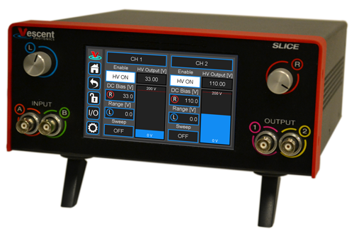
The SLICE-DHV is a low-noise, high-bandwidth, high-voltage source with DC bias control and sweep capabilities. It is designed for controlling piezoelectric transducers used for precision positioning, with particular application to laser frequency stabilization. The high-voltage output can range from 0 to 200 V, has a voltage noise <500 µV rms, can drive ±200 mA, and has an unloaded small-signal (±10 V) bandwidth >1 MHz. The SLICE-DHV also has a user-settable voltage limit for safe operation at voltages less than 200 V.
The SLICE-DHV features two Gain values: G=1 and G=20 for the input modulation signal. When G is set to 1, the output range is limited to ±10V from the user-settable DC bias voltage. When the Gain is set to 20, the modulation input signal allows access to the full range of the SLICE-DHV (0-200 V). When the Gain is set to 1, the SLICE-DHV has better noise performance than when the Gain is set to 20.
The SLICE-DHV is not recommended for applications that require a large-signal bandwidth greater than 20 Hz, defined for modulation amplitudes more than 10 V.
Model No. SLICE-DHV
Document Revision: 1
Document Last Updated on 2024/04/09 21:54
Please read Limited Warranty and General Warnings and Cautions prior to operating the SLICE-DHV.
 | Potential for electrical shock hazard. The SLICE-DHV can deliver up to 200 V at its output. Use caution when device is turned on & enabled. |
Useful Links
Click here for the Vescent manuals page.
Click here for the SLICE-DHV API.
Click here for the SLICE-DHV web page.
Click here for the Github page for SLICE-DHV firmware revisions
Please check back for added functionality. Contact sales [at] vescent [dot] com for questions and corrections, or to request added functionality.
List of Warning Symbols
 | Warning. Pay special attention to procedures and notes. If procedure is not followed carefully, damage to the SLICE-DHV or devices connected to it may occur. |
| | Potential for electrical shock hazard. |
| Important. Pay close attention to manual instructions for optimum results and in order to not damage the device. |

Description
The SLICE-DHV (figure 1) is a high-bandwidth, low-noise, high-voltage amplifier. It is intended to supply a voltage to a piezoelectric transducer (PZT) for precision motion control, including cavity length control for laser frequency stabilization applications.
Purchase Includes
- SLICE-DHV Dual-channel High Voltage Amplifier
- AC power cord with appropriate wall plug for you location (if known)
- Final Test Documentation
If your shipment is missing any items from the above list, please contact the factory.
Absolute Maximum Ratings and Power Input
Note: All modules have been designed to be operated in a laboratory environment as described in table 3.
The SLICE-DHV will accept input line voltages within the ranges shown in table 4. The SLICE-DHV is powered by Vescent's proprietary power supply technology which allows a range of voltage inputs, but retains the noise qualities of a linear supply.
| Parameter | Value | Units |
| Input Line Voltage | 100-240 | VAC |
| Frequency | 50-60 | Hz |
| Phase | 1 phase | |
| User-serviceable fuse1) | T 2.0 A L 250V | |
Proper Usage
 | If this instrument is used in a manner not specified by the manufacturer in this manual or other relevant literature, protection provided by the instrument may be impaired. |
| | Use caution when connecting the SLICE-DHV to your device. The SLICE-DHV can output up to 200 V without an input signal. It is advised that you power off the device before making connections to it. |
Always power down the SLICE-DHV completely before making connections to a laser. Never connect or disconnect the SLICE-DHVs to/from a laser with the SLICE-DHV energized.
As with any flexible instrumentation, improper usage can cause irreparable damage to the device. Please take note of all warnings and cautions.
Specifications
| Performance2) | |
| Parameter | Value |
|---|---|
| Number of Channels | 2 |
| Control Interfaces | Touch screen, USB 2.0 |
| Output Voltage Range | 0-200 V |
| Gain Ranges | Unity Gain: ±10 V around a user-settable voltage Full Range: 0-200 V |
| Modulation Gains | |
| Unity Gain Full Range | 1 V/V 20 V/V |
| Bandwidth | |
| Small Signal Large Signal | >1 MHz, unloaded <20 Hz, Cload <0.5 µF |
| Performance | |
| Output Current | ±200 mA |
| Modulation Input Voltage Range | ±10 V3) |
| Voltage Noise | <450 µV rms (10 Hz - 100 kHz) |
| Accuracy | <1% |
| Drift | 0.2 mV/°C |
| Triggering | 5V TTL |
Front Panel
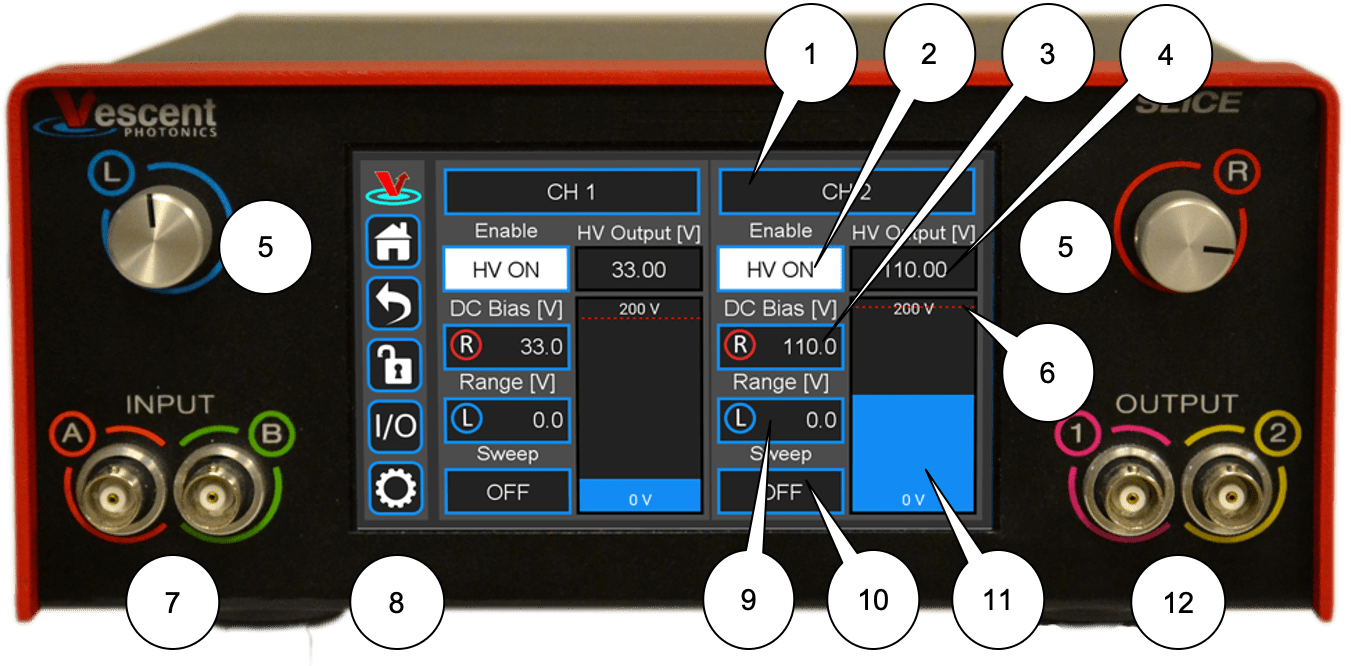
An image of the front panel of the SLICE-DHV is shown in figure 2. The functions and connections are as follows:
- Channel indicator; touch for Channel parameter settings
- Front-panel control signal inputs
Rear Panel
An image of the rear panel is shown in figure 3. The functions and connections are as follows:
- Serial Number location
- High Voltage output (CH 2; BNC)
- Modulation input (CH 2; SMA)
- Main On/Off power switch
- Fuse location5)
- AC line power in6)
- Output trigger (BNC)
- Input trigger (BNC)
- USB port for serial communication (Type B)
 Fig. 3: View of rear of SLICE-DHV
 | Use caution when connecting the SLICE-DHV to your device. The SLICE-DHV can output up to 200 V without an input signal. It is advised that you power off the device before making connections to it. |
Getting Familiar with the SLICE-DHV
The SLICE-DHV is designed to be operated from the touch screen GUI and/or serial commands delivered from a Windows® 10 PC over the USB connection on the back of the chassis. Both the touch screen and serial commands allow access to all of the SLICE-DHV functionality.
Screen Navigation
Home Screen
When presented with a given view, it is possible to select the functionality or edit the values in any field bordered in blue. When a particular field is actively being edited, its border will change to yellow. The ability to edit a yellow-bordered field will automatically time out after about 60 s and the border will turn back to blue. The Home Screen of the SLICE-DHV is shown in figure 4 and is reached by touching the home button (figure 5) in the upper left corner of the touch screen. From the Home screen, summary control over each of the two channels is possible, including setting the bias voltage. From the Home screen, you can edit the control parameters for each channel.
In general, the status displayed in an editable field is the current status (not the result of touching the button). Touch the button to select a new value/status. For instance, in figure 4 both channels are ON. Touching the ON button will stop voltage output to the given channel.
 Fig. 4: Home screen of SLICE-DHV
Control Bar
On the left edge of the screen is the Control Bar. At any given time, these buttons will have the following effect.
Home Button
 Fig. 5: Home button
Returns to Home screen.
Fig. 5: Home button
Returns to Home screen.
Back Button
 Fig. 6: Back button
Returns to previous screen. Changes will be lost if not accepted before using the Back button.
Fig. 6: Back button
Returns to previous screen. Changes will be lost if not accepted before using the Back button.
Lock Button
 Fig. 7: Lock button (shown in unlocked mode)
Locks out further modification of operation parameters. Touch to lock or unlock parameter entry. When in lock mode, it is still possible to toggle the ramp on and off, but it will not be possible to turn on the high voltage, change the bias voltage, or edit other operation parameters.
Fig. 7: Lock button (shown in unlocked mode)
Locks out further modification of operation parameters. Touch to lock or unlock parameter entry. When in lock mode, it is still possible to toggle the ramp on and off, but it will not be possible to turn on the high voltage, change the bias voltage, or edit other operation parameters.
I/O Button
 Fig. 8: I/O button
Enters the screen for programming the front-panel I/O.
Fig. 8: I/O button
Enters the screen for programming the front-panel I/O.
System Settings Button
 Fig. 9: System settings button
Enters screen for system operational settings (brightness, volume, etc.).
Fig. 9: System settings button
Enters screen for system operational settings (brightness, volume, etc.).
Entering Values
In most instances, there are two methods for entering parameter values: the physical rotary knobs on the front panel and the pop-up keypad on the touch screen. When using the knobs to change the value of a parameter, changes take effect immediately. When using the keypad, changes do not take effect until the Enter key is touched.
Rotary Knobs
If you touch an editable field for a brief moment, the border of the field will change from blue to yellow and a cursor will appear under one of the digits of the parameter value (figure 10, CH 1 DC Bias [V] field). By turning the right knob, it is possible to increase (cw) or decrease (ccw) the value of the underlined digit. Turning the left knob will change which digit is editable (cw to move to the right and ccw to move to the left). Changes made with the rotary knobs take effect immediately. Touch the yellow-bordered field again to exit the edit mode.
 Fig. 10: Knob adjustment of Bias Voltage set point for CH 1
Keypad
If you touch an editable field for a longer period of time (~3 s), a numeric keypad will appear as seen in figure 11. You can enter in the full value of the desired parameter with this keypad. Changes entered through the keypad are not enacted until the Enter key is touched.
 Fig. 11: Pop-up Keypad
The action initiated by each button of the keypad is described below.
Escape

Clear

Delete

Enter

Extendable Legs
The SLICE-DHV has four extendable legs (figure 16). Extending the front legs allows easy viewing from above (figure 1) and extending the rear legs (figure 17) allows easy viewing from below, for instance, when placed on a shelf above a laser table. Extending both the front and rear legs makes the SLICE box look like a very strange bug.


SLICE-DHV Operation
The Home screen displays the status of both channels (figure 4). The data for each channel is arranged vertically. At a glance, for each channel, the ON/OFF status, the output voltage, the nominal bias voltage, the Sweep Range (amplitude) for the internal Sweep function, and internal Sweep function status can all be read.
Bar Graph and Output Voltage Indicator
The blue bar graph and output voltage indicator (bubbles 11 & 4 in figure 2) report the high voltage output. This display is intended to display the “DC” value of the output with an update rate of about 4 Hz and will not capture faster transient behavior of the output. These displays offer quick visual identification of the output voltage and can help visualize drift in feedback control applications.
Setting the Gain on the Input Signal
The Gain on the input control signal can be set to either 1 or 20. When the gain is 1, the input modulation signal is directly summed with the DC Bias to produce the high voltage output. This mode is useful for limiting the voltage range of the high voltage output to ±10 V around the DC bias operating voltage.
When the Gain is set to 20, the input signal is multiplied by 20 and then summed into the DC bias. This mode allows the modulation input to drive the high voltage output over the entire 0 to 200 V range of the SLICE-DHV. In this mode the DC Bias defaults to zero voltage but can be adjusted to add a DC Bias to the modulation signal if desired. Note that the large-signal bandwidth will be limited when the Gain is set to 20 to less than 20 Hz, but that the small-signal bandwidth (±10V) will be identical to that when Gain = 1.
To change the Gain, touch the CH 1 (or CH 2) field at the top of the channel column. You will be presented with figure 18. Touch the Modulation Mode field to drill down to figure 19 and select either G=1 V/V; Range = ±10 V or G=20 V/V; Range = 0-200.
 Fig. 18: Setting parameters of individual channel

Choosing Current Limited or Full Bandwidth
On newer models of the SLICE-DHV, a feature was added which allows the user to switch the Modulation Mode of their unit between Current Limited, and Full Bandwidth. These two modes control the amount of drive current which can be sent through the output op-amp to modulate the load attached to HV out. In Full Bandwidth mode, the current through the op-amp is not limited, giving the SLICE-DHV a larger modulation bandwidth. The drawback, however, is that the output op-amp will occasionally go into thermal shutdown, or show distortions when driven especially hard, or with larger loads. In Current Limited mode, the output op-amp is throttled slightly to prevent the thermal shutdown and distortions seen in Full Bandwidth mode. However, using Current Limited mode slightly reduces the overall bandwidth of the system.
It is recommended to use the Full Bandwidth modulation mode if in the small signal regime (G=1 output mode, < 20 Vpp modulation), and to switch the SLICE-DHV into its Current Limited modulation mode if larger modulations (G=20 output mode, > 20 Vpp modulation) are required. This will help to prevent thermal shutdown. Certain systems may require different settings than these, though, depending on their specifics. For a more in depth discussion of choosing between Full Bandwidth and Current Limited, see our application note Load Size Selection and Limiting Factors of the SLICE-DHV’s Modulation Output.
Setting the Voltage Limit
The user can set the maximum voltage output on a given channel so as not to exceed the rated maximum for their device. From the Home screen, touch the CH 1 (or CH 2) field to see figure 18. Touch the Voltage Limit [V] field to set the maximum voltage output. The bar graph output indicator on the Home screen will scale automatically with the maximum voltage set point.
| This voltage limit circuit in the DHV hardware limits the voltage (including the modulation input) to the user defined limit when using the G=20 V/V mode. However, this hardware limit does not cap the modulation input in the G=1 V/V. Therefore, when operating in the G=1 V/V mode, if the user were to set the nominal voltage set point to the user-defined maximum voltage output point, the output with a +10 V modulation input would exceed the user-defined limit by 10 V |
Setting the Bias Voltage
To set the bias voltage about which the SLICE-DHV will operate on a given channel, touch the DC Bias [V] field on the Home screen. Depending on the length of the touch, either a view similar to figure 10 allowing rotary knob input or a keypad similar to figure 11 will be displayed. Set the nominal bias voltage.
Turning on the High Voltage
 | The SLICE-DHV can output up to 200 V without an input signal. It is advised that you power off the device before making connections to the high voltage output. |
To turn on (turn off) the high-voltage output touch the HV OFF (HV ON) field on the Home screen.
Internal Ramp Function
The SLICE-DHV has an internal ramp function for sweeping the voltage output. The ramp is a sawtooth wave.
To set the sweep rate7) of the ramp, touch the CH 1 (or CH 2) field to see figure 18. Touch the Sweep Rate [Hz] field and set the desired rate.
To set the amplitude of the ramp8), touch the Range [V] field on the Home screen and set the desired ramp amplitude.
To turn on (or turn off) the ramp, touch the Sweep OFF (or Sweep ON) field to see figure 20. Choose the desired operation mode.

Sweep Tune Mode of Internal Ramp
The Sweep Tune mode allows interactive control over the internal ramp parameters. This mode can be used to center the output of the SLICE-DHV on a particular feature of the experiment.
When in Sweep Tune mode, the Home screen will change to appear similar to figure 21, with an R in a red circle in the DC Bias field and an L in a blue circle in the Range field. In Sweep Tune mode, the user can turn the right knob to actively adjust the bias and the left knob to actively adjust the range. The rotary knob will affect the underlined digit in the respective parameter field. To change which digit is affected by rotation of the knob, push to click the knob and the cursor under the active digit will cycle through from right to left, selecting the next most significant digit after each click.

Only one Channel can have Sweep Tune mode active at any given time.
When in Sweep Tune mode:
- The rotary knob edit method is not available for the DC Bias and Range fields. Only keypad editing is allowed.
- DC Bias and Range readouts for the channel react to rotary knob actions while the Settings menu is displayed but no rotary edit is in progress on that menu.
Modulating the SLICE-DHV Output
The user can input an analog voltage signal to control the output of the SLICE-DHV. Before introducing a modulation signal, make sure you have selected the desired modulation gain.
The default modulation input port is the SMA connector on the rear panel (bubble 3, figure 3). The user can also program the SLICE-DHV to accept the modulation signal from the front-panel INPUT A for Channel 1 and INPUT B for Channel 2. Only one modulation input for a given channel can be active at any given time. To toggle between modulation input locations touch the I/O icon on the control bar and then the relevant INPUT field (A for CH1 or B for CH 2; figure 23). Select OFF for rear-panel input or Modulation Input for front-panel input.
While similar in performance, the rear-panel SMA input will have minimum noise. Use this input when possible.
Programmable Input & Output
The SLICE-DHV has two programmable inputs (labeled A & B, bubble 7 in figure 2) and two programmable outputs (labeled 1 and 2, bubble 12 in figure 2) on the front panel. It also has a rear-panel trigger input and trigger output. Touching the I/O icon on the control bar will open a screen similar to that seen in figure 22

Programmable Input
From figure 22, it is possible to assign the front-panel input as the source of the modulation/control input signal (normally assigned to the SMA connector on the rear panel of the SLICE-DHV). Touching the A Input field displays the menu seen in figure 23. From here, rear-panel modulation input (default; blank field) or front-panel modulation can be selected.
 Fig. 23: I/O programming window
Only one modulation/control input can be active at any given time for a given Channel. If the front-panel modulation/control input is activated, the rear panel modulation/control input is deactivated & vice versa.
Programmable Output
The front-panel output can be programmed to deliver a monitor of the high voltage output (figure 24). The transfer function is Vmonitor = 0.05 * Voutput
 Fig. 24: Output programming window
These front-panel inputs and outputs are mainly intended for monitoring the performance of the SLICE-DHV and as such have slower, less quiet performance than the rear-panel connections.
CH 1 can only be assigned to Input 1 and Output A. Likewise CH 2 can only be assigned to Input 2 and Output B.
Triggering
Input Trigger
The HV output can be remotely activated and deactivated by a TTL trigger introduced at the back panel of the SLICE-DHV (bubble 8, figure 3). If the Trigger In on the back side of the SLICE-DHV is activated, the high-voltage output can be shut off by pulling the input low and turned on by allowing the input to go high. (With no input, this signal is pulled high and so the HV out is active.)
In order to activate the Trigger In, touch the I/O icon on the control bar to see the I/O screen (figure 22). Touch the blue field labeled Trigger In on the selection screen in figure 25 and select which channels you wish to control with the input trigger.

Output Trigger
A TTL trigger output in sync with either of the internal ramps can be obtained at the Trigger Out (bubble 7, figure 3). Touch the I/O icon on the control bar to see the I/O screen (figure 22). Touch the blue field labeled Trigger Out for the selection screen in figure 26 and select the ramp from which channel the trigger out signal shall be derived. The end of the ramp is in sync with the falling edge of the trigger.
Only a single Channel may be chosen for outputting a trigger at any given time.

System Settings
Touching the System Settings button on the Control Bar (figure 9) will open the System Settings screen as seen in figure 27.
 Fig. 27: User-programmable system settings
Screen Brightness and Volume Adjustment
From this screen, adjustments to the brightness of the screen and the volume of the audio feedback can be made.
Input Impedance
Change the input impedance of the two front-panel input ports. Select either 50 Ω or 1 MΩ. For most applications of the SLICE-DHV, a 1 MΩ impedance should be chosen.
Using the PC Host GUI
Coming soon, please check back later.
Firmware Update
From time to time, Vescent will upgrade the firmware for controlling the SLICE-DCC. The procedure to upgrade the firmware is given here.
Serial API
It is possible to control the SLICE-DHV through serial commands. Click here to access the SLICE-DHV API.
Upgrading the SLICE-DHV firmware is not always necessary to use the Serial API. Check your installed firmware version in the settings menu against the most recent firmware version given here.
Please contact sales [at] vescent [dot] com for information.
Maintenance
There are no user-serviceable parts inside this instrument. Refer all repairs to the manufacturer. Work performed by persons not authorized by Vescent Photonics may void the warranty.
slice/dhv.txt · Last modified: 2024/04/09 21:54 by Thomas Bersano