
Table of Contents
SLICE-DCC Dual-Channel Current Controller
Model No. SLICE-DCC
Document Revision: 1
Document Last Updated on 2024/03/27 21:07
Please read Limited Warranty and General Warnings and Cautions prior to operating the SLICE-DCC.
Links
Click here for the main manuals page.
Click here for the SLICE-DCC API.
Click here for the SLICE-DCC web page.
Click here for the Github page for SLICE-DCC GUI
Click here for the Github page for SLICE-DCC firmware revisions
Please check back for added functionality. Contact sales [at] vescent [dot] com for questions and corrections, or to request added functionality.
List of Warning Symbols
 | Warning. Pay special attention to procedures and notes. If procedure is not followed carefully, damage to the SLICE-DCC or devices connected to it may occur. |
 | Potential for electrical shock hazard. |
The SLICE-DCC Current Controller is intended for driving laser diodes. When using lasers particular care must be given to avoid exposure hazards.

Description
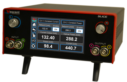
The SLICE-DCC is a low-noise, economical current controller (see figure 1). It serves as a low-noise current source providing up to 2 A. It is configured to work with a grounded cathode in either a constant current or a constant power mode.
Purchase Includes
- SLICE-DCC dual-channel Current Controller
- AC power cord with appropriate wall plug for you location (if known)
- One BNC grounding cap for door safety interlock
- Two keys for lock out
- Final Test Documentation
Absolute Maximum Ratings and Power Input
Note: All modules designed to be operated in a laboratory environment.
The SLICE-DCC will accept input line voltages within the ranges shown in table 3.
| Parameter | Value | Units |
| Input Line Voltage | 100-240 | VAC |
| Frequency | 50-60 | Hz |
| Phase | 1 phase | |
| User-serviceable fuse1) | T 2.0 A L 250V | |
Proper Usage
 | If this instrument is used in a manner not specified by the manufacturer in this manual or other relevant literature, protection provided by the instrument may be impaired. |
| | Use caution when connecting the SLICE-DCC to your diode. Diode lasers are static sensitive and can be damaged from static build up. Make sure to discharge any charge built up on your skin or clothes by using a grounding strap while making connections. |
The SLICE-DCC is designed to drive, among other devices, laser diodes, quantum cascade lasers, and semiconductor amplifiers. In order to be in US FDA compliance for driving lasers:
- There is a 5 s delay between turning on the current and the current beginning to flow. During this period, a warning light will flash on the front panel of the SLICE-DCC.
- The key switch on the rear panel must be in the on position (where you cannot remove the key).
- The interlock connector on the rear panel must be shorted either with the 50 Ω terminator supplied with the device or via an external circuit including, for instance, a (closed) entranceway.
If either the key switch is deactivated or the interlock is opened while the system is operating, the SLICE-DCC will stop delivering current and the Enable window will flash red with INTERLOCK displayed (figure 36). In order to resume normal operation, interlocks must be restored to their operational state and the window must be touched to reset the tripped interlock.
Always power down the SLICE-DCC completely before making connections to a laser. Never connect or disconnect the SLICE-DCC to/from a laser with the SLICE-DCC energized.
As with any diode laser and controller, improper usage can cause irreparable damage to the diode.
Specifications
| Performance2) | |
| Parameter | Value |
|---|---|
| Channels | 2 |
| Control | Touch Screen, GUI, Serial commands |
| Operation Modes | Constant Current Constant Power |
| Maximum Current per Channel | 200 mA 500 mA 1,000 A 2,000 mA |
| Current Noise3) 4) | 1.5 µA 4 µA 10 µA 15 µA |
| Current Modulation Input Impedance Rear Front | >20 kΩ 50 Ω or 1 MΩ |
| Modulation Bandwidth5), 6) | DC to >1 MHz |
| Modulation Input Range | ±10 V |
| Modulation Depth SLICE-DCC-200 SLICE-DCC-500 SLICE-DCC-1000 SLICE-DCC-2000 | ±10 mA ±25 mA ±50 mA ±50 mA |
| Modulation Transfer Function SLICE-DCC-200 SLICE-DCC-500 SLICE-DCC-1000 SLICE-DCC-2000 | 1 mA/V 2.5 mA/V 5 mA/V 5 mA/V |
| Current Resolution SLICE-DCC-200 SLICE-DCC-500 SLICE-DCC-1000 SLICE-DCC-2000 | 10 µA 10 µA 20 µA 100 µA |
| Drift | <25 µA/°C |
| Power Stability7) | 0.1% rms8) |
| Monitor Photodiode Input Current Range | ±5 mA |
| Maximum Compliance Voltage | 12 V |
| Triggering | TTL |
Front Panel
An image of the front panel is shown in figure 2. The functions and connections are as follows:
- Parameter input adjustment knobs
- Control signal inputs
- Signal monitor outputs
- CH status (Constant Current or Constant Power)
- Current enable (CH1 is ON, CH 2 is off)
- Current or Power (not shown) set point
- Optical Power or Diode Voltage display

Rear Panel
An image of the rear panel is shown in figure 3. The functions and connections are as follows:
- Main On/Off power switch
- AC line power in9)
- User-serviceable fuse (T 2.0 A L 250V)
- Output trigger (BNC)
- Input trigger (BNC)
- USB port (Type B)
- Interlock key receptacle
- Door interlock
- CH 2 Current output
- CH 2 Photodiode input

Getting Familiar with the SLICE-DCC
Screen Navigation
The touch screen interface and the Host GUI operate in a substantially similar way, except touch is substituted for a click in the touch screen interface.
When presented with a given view, it is possible to select the functionality or edit the values in a field bordered in blue. When a particular field is actively being edited, its border will change to yellow. The Home Screen of the SLICE-DCC is shown in figure 4 and is reached by clicking the home button (figure 5) in the upper left corner of the touch screen. From the Home screen, summary control over the two channels is possible, including setting Iset or Pset,From the Home screen, you can edit the control parameters for each channel.
In general, the status displayed in an editable field is the current status (not the result of touching the button). Touch the field to select a new value/status. For instance, in figure 4 both channels are in stand by. Touching the OFF button will initiate current delivery to the given channel.
 Fig. 4: Home screen of SLICE-DCC
Control Bar
On the left edge of the screen is the Control Bar. At any given time, these buttons will have the following effect.
Home Button
 Fig. 5: Home button
Returns to Home screen (figure 4).
Fig. 5: Home button
Returns to Home screen (figure 4).
Back Button
 Fig. 6: Back button
Returns to previous screen. Changes will be lost if not accepted before using the Back button.
Fig. 6: Back button
Returns to previous screen. Changes will be lost if not accepted before using the Back button.
Lock Button
 Fig. 7: Lock button (shown in unlocked mode)
Locks out further modification of parameters. Touch to lock or unlock parameter entry. When in lock mode, it is still possible to toggle the current on and off, but it will not be possible to change the set point or other operation parameters.
Fig. 7: Lock button (shown in unlocked mode)
Locks out further modification of parameters. Touch to lock or unlock parameter entry. When in lock mode, it is still possible to toggle the current on and off, but it will not be possible to change the set point or other operation parameters.
I/O Button
 Fig. 8: I/O button
Enters the screen for programming the front-panel I/O.
Fig. 8: I/O button
Enters the screen for programming the front-panel I/O.
System Settings Button
 Fig. 9: System settings button
Enters screen for system control settings (brightness, volume, etc.).
Fig. 9: System settings button
Enters screen for system control settings (brightness, volume, etc.).
Entering Values
In most instances, there are two methods for entering parameter values: the physical rotary knobs on the front panel and the pop-up keypad on the touch screen. When using the knobs to change the value of a parameter, changes take effect immediately. When using the keypad, changes do not take effect until the enter key is touched.
In order to afford maximum resolution, the least significant digit will not necessarily change to precisely your target value and will be coerced to the nearest acceptable value, which is limited by the digitization scheme for the set point. For instance, you may select a set point current of 151.13 mA, but the closest allowed digitized value may be 151.14 mA.
Rotary Knobs
If you touch an editable field for a brief moment, the border of the field will change from blue to yellow and a cursor will appear under one of the digits of the parameter value (figure 10). By turning the right knob, it is possible to increase (cw) or decrease (ccw) the value of the underlined digit. Turning the left knob will change which digit is editable (cw to move to the right and ccw to move to the left). Changes made with the rotary knobs take effect immediately.
 Fig. 10: Knob adjustment of Current set point for CH 1
Keypad
If you touch and hold an editable field such as the current set point, a numeric keypad will appear as seen in figure 11. You can enter in the full value of the desired parameter with this keypad. Changes entered through the keypad are not enacted until the Enter key is touched.
 Fig. 11: Pop-up Keypad
The action initiated by each button of the keypad is described below.
Escape

Clear

Delete

Enter

Extendable Legs
The SLICE-DCC has four extendable legs (figure 16). Extending the front legs allows easy viewing from above (figure 1) and extending the rear legs (figure 17) allows easy viewing from below.


SLICE-DCC Operation
The Home screen displays the status of both channels (figure 4). The data for each channel is arranged vertically. At a glance, for each channel, Iset, and Compliance Voltage can be read. Touching the blue window labelled Voltage [V] will cause this window to toggle from displaying Compliance Voltage to displaying dissipated Power.
Laser and Photodiode Connections
Connection to Laser Diode
The SLICE-DCC requires that the cathode of the laser diode is at ground (figure 18). The anode is connected to the center conductor of the SMA connector on the rear of the SLICE-DCC and the cathode is connected to the sheath.

Connection to Monitor Photodiode
Either of the two configurations of the monitor photodiode seen in figure 19 will work for the signal proportional to the laser diode power for operating in Constant Power mode. Depending on how you have completed the monitor photodiode circuit, you may have to adjust the sign of the Constant Power feedback loop.

Setting the Operation Mode
The SLICE-DCC has two operation modes: Constant Current and Constant Power. The operation mode, as with most other operating parameters can be set independently for each channel. To toggle between Constant Current and Constant Power modes, from the Home screen, touch the window labelled either CH X Constant Current or CH X Constant Power. If the channel is in Constant Current Mode, you will be presented with the window seen in figure 20.
 Fig. 20: Setting Maximum Current
If the channel is in Constant Power mode, you will be presented with the window seen in figure 21.
 Fig. 21: Selecting Constant Power mode parameters
Touching the Window labeled Control Mode will allow you to toggle the channel back & forth between Constant Current and Constant Power modes as seen in figure 22.

Setting the Current Limit
The user can set a maximum deliverable current so as not to exceed the rated maximum for their device. From the Home screen, touch the window labelled either CH X Constant Current or CH X Constant Power. Depending on the operation mode, you will be presented with either figure 20 or figure 21.
Touch the Current Limit window and enter the maximum allowed current (in mA) as in figure 23.
 Fig. 23: Set Current Maximum
Setting the Operating Current in Constant Current Mode
In Constant Current mode a linear regulator minimizes current noise & fluctuations.
To set the current set point from the home screen, touch the Set point window for the desired channel. A long touch will cause a keypad to appear (figure 24). Enter desired value and touch the accept button.
A short touch will highlight the Setpoint window in yellow (figure 10). Use rotary knobs to select digit to edit (left knob) and value for digit (right knob).
Fig. 24: Keypad adjustment of Current set point for CH 1
Setting the Operating Power in Constant Power Mode
To set the power set point in Constant Power Mode from the home screen, touch the window labelled Setpoint [mW] and enter the target power level (figure 25). If the window is labelled Set Point [mA], the device is in Constant Current mode and must first be switched to Constant Power mode.
It is possible to adjust the Power Setpoint when the system is either ON or in Standby mode.

Enabling Current
When the blue window labeled Enable reads OFF, the system is in standby mode and no current is delivered. Briefly touching this window will, after a 5 s pause during which a warning light will flash, cause current to begin to flow and the window will read ON.
Rear-Panel Modulation
On the rear panel of the SLICE-DCC is an SMA input for servoing or modulating the current output. (figure 3, item 9). The transfer function for this input depends on the current capacity (see table 4). The input range is ±10 V. The current can be modulated over the full range of current except for the 2,000 mA model which can only swing ±50 mA. The 3-dB bandwidth of this modulation input is DC to 1 MHz.
It is also possible to introduce a modulation/control signal from the front-panel input BNC. Only one input port can be active at a time.
 | Although there is protection circuitry to reduce reverse biasing the diode, negative voltages as high as -0.5 V can be applied. It is not advisable to modulate under conditions where negative voltage would be applied. Avoid low current set points with large-amplitude modulation. |
| | Make sure that the modulation input cannot drive the current above the maximum rated current for your device by setting the Current Limit appropriately. |
Constant Power Mode
In Constant Power mode, the SLICE-DCC accepts a current input signal from the output of a photodiode (often internally mounted with the diode laser). This signal is conditioned by a trans-impedance amplifier and used as an error signal. It is further processed by a loop filter to provide a correction signal to the current to maintain constant power.
 | Warning. Make sure the Current Limit is set below the recommended maximum current for your laser diode and that the monitor photodiode is working and delivering a signal to the SLICE-DCC before engaging Constant Power mode. If a signal proportional to the laser power from the monitor diode is not delivered to the SLICE-DCC, the current may ramp to its maximum allowed value when Constant Power mode is engaged. |
- Connect the output of the monitor photodiode to the CH X Photodiode Input connector (labelled “10” in the back-panel image) on the back of the SLICE-DCC.
In order for Constant Power mode to operate correctly, the user must set three control parameters: the responsivity of the monitor photodiode, the gain of the loop filter, and the polarity of the photodiode response. Before setting these control parameters. First set the SLICE-DCC in Constant Power mode and set the Power Setpoint. From the home screen, enter the CH X Settings screen by tapping the window labelled CH X: Constant Power. Enter values for Detector Response, Gain, and monitor photodiode Polarity.
- Enter the value of the detector response supplied in the documentation that came with your monitor photodiode. (figure 26)
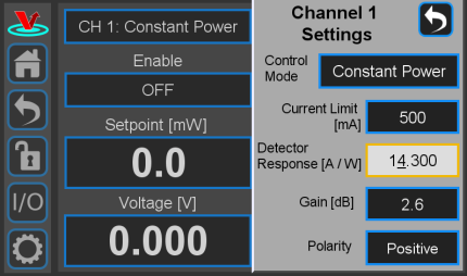 Fig. 26: Setting the detector response for Constant Power mode
 - Turn the Gain all the way to 0 (zero). Turn the system ON to deliver current to the diode. Slowly turn up the Gain until the power begins to oscillate (figure 27). (Hint; It is easiest to adjust the gain for this step via the knobs as opposed to through the keypad.) Turn down the Gain until oscillation stops.
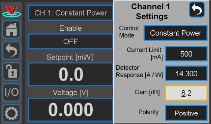 Fig. 27: Setting the Gain for Constant Power
 - If more Gain moves the power away from the set point, switch the polarity from Positive to Negative (or vice versa).


Programmable Input & Output
The SLICE-DCC has two programmable inputs (labelled A & B) and two programmable outputs (labelled 1 and 2) on the front panel. It also has a rear panel trigger input and trigger output. Touching the I/O icon on the control bar will open a screen similar to that seen in figure 28, From here, it is possible to assign control information input to the two inputs and system performance data to the two outputs,
 Fig. 28: I/O programming window
These front-panel inputs and outputs are mainly intended for monitoring the performance of the SLICE-DCC and as such have slower, noisier components than the rear-panel connections.
Programmable Input (Front-panel Modulation)
From figure 28, if one touches either the A or B input window, the choices for input for that channel are presented (figure 29).
 Fig. 29: Input choice for front-panel input
The only input option is a modulation signal. The SLICE-DCC can respond to a modulation or control signal over a bandwidth of DC to 1 MHz. Only one of the two modulation input ports (rear-panel SMA, figure 3, item 9 or front-panel BNC, figure 2, item 2) can be active at any given time. Activating the front-panel input via the screen in figure 29 automatically disconnects the rear-panel input.
The depth and index of modulation varies depending on the current capacity of the particular SLICE-DCC unit. See table 4.
Programmable Output
From figure 28, if one touches either the 1 or 2 output window, the choices for output for that channel are presented (figure 30).
 Fig. 30: Output choices for front-panel input
One can choose to monitor the current output and/or the optical power as measured at the photodiode input.
Triggering
External control of the SLICE-DCC is accomplished via a TTL trigger.10) 0 to 0.8 V TTL is low and 2 to VCC is TTL high.
Trigger Out
The Trigger Out on the back panel of the SLICE-DCC can be programmed to go high if an interlock (key or door) is opened. The screen shown in figure 31 will be reached by touching I/O > Trigger Out. Checking the box will cause the Trigger Out to go high if either the door interlock or the key interlock is opened.
 Fig. 31: Setting an output trigger
Trigger In
The input trigger can be used to turn on or off the current for either or both channels. From any screen, touch I/O > Trigger In. You will be presented with the window in figure 32. Select which channels you wish to control with the incoming trigger. In figure 33, current to CH 2 will be disabled if the Trigger In goes high.


System Settings
Touching the System Settings button on the Control Bar (figure 9) will open the System Settings screen as seen in figure 34.
 Fig. 34: User-programmable system settings
User Interface Appearance
From this screen, adjustments to the brightness of the screen and the volume of the audio feedback can be made.
Input Impedance
Change the input impedance of the two front-panel input ports. Select either 50 Ω or 1 MΩ.
SLICE Firmware
Current firmware versions are reported here.
From time to time, Vescent will upgrade the firmware for controlling the SLICE-DCC. The procedure to upgrade the firmware is given here.
Host GUI
If accessed through a PC Host GUI, the Settings screen (figure 35) also has the ability to assign the COM port for the device. If viewed through the GUI, there are no brightness or volume controls as these should be set on the PC directly.
 Fig. 35: User-programmable system settings from host GUI
Error States
Interlock Open
If either the key switch is deactivated or the interlock is opened while the system is operating, the SLICE-DCC will stop delivering current and the Enable window will flash red with INTERLOCK displayed (figure 36). In order to resume normal operation, interlocks must be restored to their operational state and the window must be touched to reset the tripped interlock.
 Fig. 36: Interlock Open state
Open Circuit
If the SLICE-DCC attempts to deliver current, but is unable to do so, it assumes an open circuit fault. The Enable window on the Home screen for that channel will flash red with the warning “Open Circuit/Over Voltage” (figure 37).

Using the Host GUI
It is possible to control the SLICE-DCC from a Windows®-based PC using the GUI written for this purpose. In order to use the GUI, you must first download the latest version, connect the PC to the SLICE-DCC, and assign a COM port to the SLICE-DCC. The following describes the steps involved.
- Download and store the latest GUI executable from the Vescent FTP site (or request copy of executable GUI from sales [at] vescent [dot] com).
- Connect the SLICE-DCC to the PC using a USB type B cable.
- Turn on the SLICE-DCC.
- On the PC, double click on the SLICE-DCC GUI to start the GUI.
- On your PC, go to Start > Control Panel > Device Manager > Ports
- Identify which COM Port is labeled “STMicroelectronics Virtual COM Port (COMXX)” or similar. Note the value of XX.
- On the SLICE-DCC GUI, click on the Settings icon
 to get to the window shown in figure 38.
 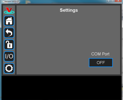 Fig. 38: Settings screen when viewed by GUI
 - Click on the OFF button below COM Port. You should see a menu similar to the one shown figure 39. NOTE: The COM port numbers may differ from those shown below.
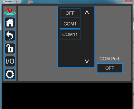 Fig. 39: COM port selection
 - Select the COM port identified in the step above (usually the last COM port in the list; COM11 in this example). The window in figure 40 should appear if the connection is successful.
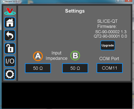 Fig. 40: Ready to upgrade


The GUI should now actively control the SLICE-DCC. You should only have to do the above steps once from a given PC. After assigning the COM port, the system will recognize the device in the future (unless you reassign the COM port to another device).
Firmware Update
From time to time, Vescent will upgrade the firmware for controlling the SLICE-DCC. The procedure to upgrade the firmware is given here.
Serial API
It is possible to control the SLICE-DCC through serial commands. Click here to access the SLICE-DCC API.
Upgrading the SLICE-DCC firmware is not always necessary to use the Serial API. Check your installed firmware version in the settings menu against the most recent firmware version given here.
Please contact sales [at] vescent [dot] com for information.
Maintenance
There are no user-serviceable parts inside this instrument. Refer all repairs to the manufacturer. Work performed by persons not authorized by Vescent Photonics may void the warranty.
Warnings and Faults
Hardware Temperature Exceeded
Displayed when hardware temperature exceeds a safe limit for an individual channel. Turn off the SLICE-DCC and let the unit cool for several minutes. If problem persists, contact Vescent.
 Fig. 41: Hardware Temperature Exceeded Error Message
Internal Case Temperature Exceeded
Dffects both channels and is displayed when the temperature inside the case exceeds a safe limit. Turn off the SLICE-DCC and let the unit cool for several minutes. If problem persists, contact Vescent.

Interlock
Displayed on both channels when the interlock circuit is open. Double check that the Interlock Key is inserted and in the “Closed” position, and that the Interlock BNC port is connected to either an interlock system, or the 50Ω terminator cap.

Open Circuit Over Voltage
Displayed on a channel that is started without a load attached. Double check connections on both the SLICE-DCC and the attached load. If problem persists, contact Vescent.

Possible Fault Detected
Displayed when current is being output in spite of the channel being disabled.The appearance of this fault indicates a potential hardware failure. Do NOT continue to use unit, and contact Vescent immediately.
