
This is an old revision of the document!
Table of Contents
Offset Phase Lock Servo Board
Model No. ICE-OPL1
Document Revision: 0.1
Document Last Updated on 2021/08/26 14:26
Please read Limited Warranty and General Warnings and Cautions prior to operating the ICE-OPL1.
Description
«Description of OPL1»>
Absolute Maximum Ratings
Note/Todo: These ratings are for CP1, not OPL1. They are nearly the same board, though! Note: All modules designed to be operated in laboratory environment
| Parameter | Rating |
|---|---|
| Environmental Temperature | >15°C and <30°C |
| Environmental Humidity | <60% |
| Environmental Dew Points | <15°C |
Specifications
Note/Todo: These specifications are for CP1, not OPL1.
| ICE-CP1-200 | ICE-CP1-500 | Units | |
|---|---|---|---|
| Current Source | |||
| <html> </html>Current range | 0-200 | 0-500 | mA |
| <html> </html>Current setpoint resolution | 200 | 500 | μA |
| <html> </html>Current noise density1) | <100 | <200 | pA / <HTML> √Hz </HTML> |
| <html> </html>RMS Noise (10Hz - 100kHz)2) | <50 | <100 | nA |
| <html> </html>RMS Noise (10Hz - 1MHz)3) | <100 | <150 | nA |
| <html> </html>RMS Noise (10Hz - 10MHz)4) | <300 | <500 | nA |
| <html> </html>Absolute accuracy | 2 | % | |
| Offset Phase Lock Servo Input Signal | |||
| <html> </html>Min Offset Frequency | 250 | MHz | |
| <html> </html>Max Offset Frequency | Min: 9, Typical: 105) | GHz | |
| <html> </html> Max Electronic Beat-Note Input <html> </html><html> </html>(ICE-CP1-SMA) | 10 | dBm | |
| <html> </html> Min Electronic Beat-Note Input <html> </html><html> </html>(ICE-CP1-SMA) | -10 | dBm | |
| <html> </html> Min Electronic Beat-Note S/N <html> </html><html> </html>(ICE-CP1-SMA) | >50 | dB | |
| <html> </html> Max Optical Beat-Note Input <html> </html><html> </html>(ICE-CP1-FC) | 1 | mW | |
| <html> </html> Min Optical Beat-Note Input <html> </html><html> </html>(ICE-CP1-FC)6) | 50 | μW | |
| <html> </html> Front-panel Input Connection <html> </html><html> </html>(ICE-CP1-FC)7) | SC | ||
| <html> </html> Front-panel Input Connection <html> </html><html> </html>(ICE-CP1-SMA) | SMA | ||
| Offset Phase Lock Servo Performance | |||
| <html> </html>Bandwidth8) | TBD | MHz | |
| <html> </html> Interval reference frequency drift | +/-20 | ppm | |
| <html> </html> PFD Noise9) | -213 | dBc/Hz | |
| Loop Filter Parameters | |||
| <html> </html>Proportional Gain | -72 – 0 | dB | |
| <html> </html>Proportional Gain Resolution | 2 | dB | |
| <html> </html>Integrator | 3, 10, 30, 100, 300 | kHz | |
| <html> </html>Differential | Off, 10, 30, 100, 300 | kHz | |
| <html> </html>Differential Gain | 18 | dB | |
Setting the Offset Frequency
Two numbers control the offset frequency of the ICE-OPL1: The divider setting N and the reference frequency. The divider setting N can be set to N=8,16,32 or 64. The reference frequency can be generated internally with a range from 50 - 240 MHz. A sequence of frequencies and frequency ramps can be programmed using OPL1's DDS Queue. Alternatively, an external frequency reference can be provided (external frequency must be from 32 MHz - 240 MHz). The offset frequency of the laser is given by the following formula:
<html><center></html> Offset = N * Reference Frequency <html></center></html>
The table below shows the offset range for different values of N and using the internal or external frequency reference.
Controlling Offset Frequency with the DDS Queue and Manual Controls
The Direct Digital Synthesizer (DDS) generates frequencies against which the user can compare and lock an input beatnote. If the user enables the use of an internal reference frequency, it is the DDS that creates that frequency. The DDS output can be manually controlled, or the on-board micro controller can be programmed to execute a sequence of frequency profiles using the DDS. This section details the use of these systems.
The DDS Queue GUI
The DDS can be controlled directly from the GUI, or using a series of ascii commands. Due to the complexity and large amount of data transfer involved in programming the DDS Queue, it is highly recommended that users use the GUI (shown below with an example queue).

New Profile
When clicked, a window opens in the GUI that allows the user to define a new profile for the DDS to execute. Available profile types are Single Tone and Frequency Ramp.
Edit Profile
Opens a window to select a profile to edit. This window can also be opened by clicking the [edit] button next to playlist entries.
Delete Profile
Opens a window where the user can select a profile to remove from the program. Deleting a profile will also delete playlist entries that are tied to the deleted profile.
Save Settings
Opens a file dialog where the user can save the current state of the OPL1 GUI, including the currently defined profiles, currently defined playlist, and currently defined playlist interrupt triggers. The save format is JSON, so the user may open the saved .ddsq-settings file in any plain text editor and manually adjust the saved parameters.
Load Settings
Opens a file dialog where the user can pick a .ddsq-settings file to load. Loading a file will overwrite any defined profiles, playlists, and playlist interrupt triggers.
Execute Sequence
This button programs the current profiles and current playlist into the OPL1 microcontroller. Out of necessity multiple actions occur when this button is pressed. First, any currently executing DDS Queue is aborted to prevent conflicts. The profiles are then programmed into the microcontroller’s memory one by one. The playlist is programmed next. Once the Queue is in the microcontroller, the first profile is pre-programmed into the DDS but not triggered (this is left to the user). Finally the DDS Queue is marked active, which prevents manual-mode controls from sending commands to the device.
Abort Sequence
Aborts any currently running DDS Queue and re-enables manual-mode controls.
Trigger Event
This sends a #doevent N (where N is the event address, ranging from 1 to 7) command to the master ICE board, which relays the command to EVERY connected board. Sending the event trigger to every board in ICE allows the user to synchronize various board events to the same trigger, at the expense of limiting the number of available trigger addresses. For any profile that has a programmed interrupt trigger of “Event System”, the user must press this button to trigger the end of that profile and move on to the next profile.
Event Address:
When this value is adjusted, it sends a command to the board indicating which event address the DDS Queue should listen to for profile transitions. So if the user puts the number 3 in the Event Address box, and then presses Trigger Event, the GUI will send the command #doevent 3 to the master board. Since the DDS Queue has been programmed to listen to event address 3, it will trigger the transition to the next profile in the queue, if possible. If the user puts the number 2 into the Event Address box and then manually sends the command #doevent 3, the DDS Queue will do nothing, since it is now listening for a trigger signal on event address 2.
NOTE: This value will not actually be sent to the device unless the user presses <ENTER> or switches focus to another GUI component. Just changing the number alone does NOT send the new event address to the device.
Current Step:
The value or text presented here tells the user the current state of the DDS Queue. Possible states include: N/A, Programmed and Idling, Queue Inactive, Error. Restart., and an integer number. The meanings of these states is as follows:
- N/A - Only appears on start up before any user input occurs.
- Programmed and Idling - The users playlist has been programmed into the microcontroller, and the first profile has been programmed into the DDS. The DDS is still outputting the frequency determined by the manual-mode controls, as the first profile has NOT been triggered.
- Integer Number - the index of the profile that is currently being outputted by OPL1.
- Queue Inactive - execution of the DDS Queue is either complete or has been aborted.
- Error. Restart. - The GUI received an unexpected or erroneous data from the board while trying to determine the current queue step. Try restarting queue execution by pressing the Execute Seq. Button. If that does not fix the error, the device is likely in an unknown state and should be power cycled.
Add Element at:
This allows the user to insert a profile into the queue at any index (starting at 0). If the index is greater than the largest index in the playlist, the GUI will add the element at the end of the list. The profile added will always be the first profile defined, so it is likely the user will have to adjust the new element to the desired profile and interrupt trigger.
Preview
Reads the current state of the user defined playlist and generates a graph of the predicted offset frequency (the product of the DDS frequency and N Div). The preview is drawn using the profile defined durations even if a profile transition is manually triggered. If the interrupt trigger for any profile in the list is “Event System” then the actual duration of that profile is indefinite, as it depends on user input.
Playlist Profiles
This is the list of defined profiles that will be programmed into the device and executed. Each element can be any one of the defined profiles, so the user can re-use profiles as needed.
Playlist Interrupt Triggers
For each profile in the playlist, the user can select how the DDS will transition out of that profile.
- Event System - This interrupt type will have the DDS output that profile until the user presses the Trigger Event button or sends a “#doevent «N»” command where N is the event address set for DDS Queue transitions.
- Go to next profile - This interrupt will have the board automatically transition to the next profile once the user programmed profile duration expires.
For example, consider the following playlist
- Profile 0 - Go to Next Profile
- Profile 1 - Event System
When the user executes this sequence, the following steps occur:
- DDS Queue is cleared and reprogrammed with the user's new playlist, wait for the user to trigger the sequence by pressing the Trigger Event button or sending a “#doevent «N»” command.
- When triggered, activate profile 0. Set an internal timer for the duration of profile 0. Program the DDS for profile 1, but DO NOT activate profile 1.
- When the timer expires, it will activate profile 1. Since there are no more profiles to execute, it will not program the DDS for another step. The internal timer will be disabled, since the interrupt type for profile 1 is “Event System”. Instead, it will wait an indefinite amount of time for the user to trigger the transition event.
- When the user triggers the next event, the DDS will transition out of queued mode into manual mode. Whatever values the user has set in the manual mode controls will be sent to the device and the offset frequency will change accordingly.
Creating a New Single Tone or Frequency Ramp Profile


Running the Queue
Once the user has created the desired profiles, they can use the 'Preview' Button to see the planned offset frequency as a function of time. Below is the preview for an example sequence.

The queue is preprogrammed into the OPL1 micro-controller at the beginning of queue execution, but the DDS needs to be reprogrammed for each individual profile at run-time. It is desirable to minimize the latency between triggering a switch in DDS profile and the actual change in offset frequency. In order to do this, the DDS is programmed with the next profiles parameters immediately after the current profile is triggered. By doing this, only a single pin needs to be flipped on the DDS when it comes time to transition to the next profile, as all of the necessary data has already been written to the pertinent registers. This sequence is shown below.

The programming of each profile into the DDS takes time. The more complex the profile, the more time it takes to program it. A simple profile, like a single tone profile, will take less time to program than for a frequency ramp profile. This is shown in the figure below.

A Note on Mixing Frequency Ramp Direction
The on board DDS is only capable of performing a positive frequency ramp (i.e. 100 MHz to 200 MHz). A negative ramp can be achieved by taking advantage of alias frequencies (where the programmed output frequency is actually greater than the clock frequency on the DDS). In this fashion, the DDS is programmed to ramp from something like 800 MHz to 900 MHz, but due to aliasing the output frequency is a negative ramp from 200 MHz to 100 MHz.
We experimented with this methodology and determine that it does not introduce significant phase noise. The only problem arises when a transition occurs between a profile that needs aliasing and a profile that does not need aliasing (for example, switching from a negative ramp to a positive ramp). If the user uses only negative ramps or only positive ramps, the controller will automatically change its execution mode to prevent this phase glitch.
However, if the user requires a profile sequence that includes both positive and negative ramps, the transition between alias frequency profiles and non-alias frequency profiles will introduce a phase glitch of a value between 0 and PI. We believe this glitch can be ignored, as it should be corrected by the servo, but it may be worth considering how this glitch could impact your experiment.

Manual Control
The GUI can be used to manually control the offset frequency output by OPL1. The manual control components are found to the left of the DDS Queue pane. The offset frequency can be manipulated by changing the Int. Ref. Frequency or changing the N Div setting. The Servo Offset and Phase Frequency Discriminator polarity can also be manually adjusted. Manual controls are locked when the DDS Queue is active, as shown below.

Understanding Gain in the OPLS
The charge pump (CP) output is proportional to phase-error when phase-locked, but the slope is proportional to the value of N. This means that when N is increased, the same voltage on the CP monitor reflects twice as much phase-error. The result is that the input to the loop filter has half as much gain with N=16 than with N=8. To compensate, the OPLS internally increases the gain of the Loop Filter by a factor of N so the user does not see a change in the closed-loop gain when changing the value of N.
Understanding the Transfer Function
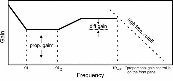 Fig. 1: Schematic of the OPLS right-side panel,showing the configurable transfer function and its user-controls.
The charge pump in the OPLS outputs a signal proportional to the phase-error and the transfer function is as shown in figure 1. However, the OPLS will typically be used to control a frequency-tunable device (such as a laser). In this configuration, the effective loop filter is not the one shown in figure ##, but includes a extra integration corresponding to converting the phase-error input to a frequency error. Thus, ωI sets the frequency transition from single-integration to double-integration and ωI from single-integration to proportional feedback. It is important to understand this 'hidden' integrator when configuring the loop filter parameters.
Calculating Phase Noise
The phase-noise specified in Section 1.3 is referenced to the phase frequency detector (PFD) at 1 Hz. To convert that to the noise measured on the actual beat-note, it must be rescaled with the following formula:
<html><center></html> D2-135 Phase-Noise Floor = -213 + 20Log(N) + 10Log(FREF)<html></center></html>
where N is the value of the divider and FREF is the reference frequency as measured in Hz. For more details, please see http://www.vescent.com/2012/calculating-phase-noise-from-the-d2-135/ .
I/O (ICE-BOX)
Only when purchased with the ICE-Box.
Beat Note Input
The Front Panel for the ICE-CP1 has four SMA or FC connectors. The top connector (SMA for ICE-CP1-SMA, FC for ICE-CP1-FC) is the beat note signal input. When FC, this input should be a <1 mW signal containing overlapped light from both lasers. When an SMA, this input should be an electrical signal, typically the output of the D2-160.
External Reference Frequency Input
The Front Panel for the ICE-CP1 has four SMA or FC connectors. The second top-most connector is an SMA input for the external frequency reference. The input is AC coupled and 50 Ω terminated. Max power is 10 dBm.
Beat Note Monitor
The Front Panel for the ICE-CP1 has four SMA or FC connectors. The second bottom-most connector is an SMA which is the digitized (i.e. square-wave) version of the input beat-note after a divide-by-2. For example, if the input beat note is 6 GHz, the monitor will have a 3 GHz output. The signal is ~0 dBm in power regardless of the strength of the input beat-note signal.
Laser Current
The Front Panel for the ICE-CP1 has four SMA or FC connectors. The bottom SMA goes to the laser and drives positive current to the laser. The center conductor of the SMA goes to the laser anode.
I/O (OEM Only)
Only for OEM versions of the ICE-CP1 purchased without the ICE-Box.
 Fig. 2: Connector and component positions on PCB.
Beat Note Input
The ICE-CP1 has one SMA connector which is the beat note signal input. This signal should be an electrical beat -note between -10dBm and 10dBm of electrical power. Input is 50 Ω terminiated.
External Reference Frequency Input
The ICE-CP1 has three UMCC (Molex PN: 0734120110) connectors. The one labelled “Ext Ref” is an UMCC input for the external frequency reference. The input is AC coupled and 50 Ω terminated. Max power is 10 dBm.
Beat Note Monitor
The ICE-CP1 has three UMCC connectors. The one labelled “BN Mon” is an UMCC containing is the digitized (i.e. square-wave) version of the input beat-note after a divide-by-2. For example, if the input beat note is 6 GHz, the monitor will have a 3 GHz output. The signal is ~0 dBm in power regardless of the strength of the input beat-note signal.
Laser Current
The ICE-CP1 has three UMCC connectors. The one labelled “Laser” goes the laser and drives positive current to the laser. The center conductor of the UMCC goes to the laser anode.
Quick Start Commands Guide (Laser Current)
Please see the Quick Start Commands Guide (Laser Current) in the ICE-CS1 manual.
Quick Start Commands Guide (Offset Phase Lock Servo)
Please see Overview of Commands and Basic Usage, Common Commands to all Slave Boards and Current Controller & Offset Phase Lock Servo Commands for a complete command list. Set the ICE-MC1 to communicate with the slot that this ICE-CS1 is in (see Master and Control Board Overview for details).
This content is not yet available, sorry.