
Table of Contents
Quick Setup Instructions

Document Last Updated on 2021/08/26 14:26
Electronic Modules Initial Setup
Place the three electronics modules (System Power, Laser Controller, and Laser Servo) in a row as shown on the right (order is not important).
On the back of the modules, attach the two 9-pin D-sub cables across adjacent modules. (If you have an older system, you will have plug block, not cables.) See pictures below. Make sure the security key is in place on the Laser Controller. When the key is in the vertical position (clockwise) it cannot be removed from the Laser Controller and is in the activated position. You must either have the 50 Ω terminator in place on the Remote Interlock BNC input or have it wired to a door or other safety interlock in your lab.


On the Laser Controller, in the bottom left corner, make sure that the LASER switch is in the OFF/RESET (down) position.
Make sure the power switch on the System Power module is in the OFF (down) position. Plug power cable into back of System Power module.
Optic Modules Initial Setup

Place the Laser Module on an optics table and bolt to table with (4) 1/4-20 screws.
Align the Spectroscopy Module to the Laser Module. (If using a D2-110, place Spectroscopy Module at least 3” away from the DBR Module.) The magnetically shielded D2-210 may be placed closer to the Laser Module.
To help with optical alignment, loosen the four screws that hold each module and gently register the modules by pushing against the screws in the same direction. (This is how they were aligned at Vescent.)
Cabling & Power
Never connect or disconnect the D2-105 to/from a laser with the D2-105 energized. Always power down the D2-105 completely before making connections to the laser.
Never connect any device to the D2-005 power supply when it is switched on and supplying power. Always turn off the power supply, make connections to the devices, and then re-energize the power supply.
Locate the 6 ft connector cable assembly with SMA connectors on both ends. Plug the SMA connector into the LASER CURRENT OUTPUT plug and the Hirose connector into the LASER TEMP OUTPUT on the Laser Controller. Make sure that the nearby Laser switch is in the OFF/RESET position (down). While grounded, remove the SMA terminator connected to the Laser. Connect the other end of the SMA cable and Hirose connectors to the DBR module.

Find the 6 ft cable assembly with an SMA on one end and a BNC connector on the other. It will be bundled with a cable that has a Hirose connector on at least one end. If you have the D2-210, the other end of this cable will be a D-sub 9-pin connector. If you have a D2-110, it will be a second Hirose connector. Plug the BNC end into the ERROR INPUT on the Laser Servo. Plug the SMA end into the Spectroscopy Module. Connect the Hirose connector to the Spectroscopy Module. If you have a D2-210, connect the other end of this cable to a spare D-sub 9-pin power I/O on the back of the D2-005 or other D2 module. If you have the older D2-110 Spectroscopy Module, connect the Hirose connector on the on the free end of the cable to the Temp Cntl Hirose on the D2-125-T.
Take one short (~1 ft) BNC cable (not included) and connect it from the CURRENT SERVO INTPUT on the Laser Controller to the SERVO OUTPUT on the Laser Servo.
For Peak-Lock Only: Connect one short (~1 ft) BNC cable (not included) from the RF INPUT on the Laser Controller to the RF OUTPUT on the Laser Servo.
Flip the switch on the System Power Module to the ON position. Three LED's (+5 V, +15 V, -15 V) on the System Power modules should glow blue.
Both the Laser Controller module and the Laser Servo module should have a blue LED glowing next to the label POWER. If not, check that the power cables, safety key, and interlock are properly connected on the back.
Laser Controller
Flip the TEMP LOCK switch on the Laser Controller into the SERVO position. A green light next to T2 should turn on in ~1 minute. In ~2 minutes, the T1 green light should also turn on. The LEDs turn red if the temperature servo senses an error condition, or if the laser is not between 0 and 50°C. They will remain red until LASER TEMP OUTPUT is connected (open condition), and when the TEMP LOCK is in the STANDBY position.
Rotate the display selector knob in the upper right corner of the Laser Controller until the “Ilim” indicator is lit. Make sure the current limit value shown is below the value shown in your final test report included with your laser system.
The Laser Controller has two safety interlocks. If either interlock is tripped, the laser will turn off and stay off until the interlock condition has been fixed AND the Laser switch has been moved from “off/reset” position to the “on” position. To turn the laser on for the first time follow the subsequent procedure:
- Place the front panel Laser switch in the “OFF/RESET” position.
- Place the included terminator on to the back-panel “remote interlock” BNC.
- Take the key that was taped to back of the Laser Controller and place it in the back-panel Laser Enable keyhole and rotate the key 90 degrees (the key should be vertical).
- Now that both interlocks are enabled, flip the Laser switch into the “ON” position. The green “Laser On” light should turn on and 5 seconds later the laser should turn on.
Rotate the display selector knob in the upper right corner of the Laser Controller until the LED underneath the label “I” is lit. Adjust the COURSE CURRENT to the value given in the accompanying paperwork to place the laser on the D2 (or D1) hyperfine transitions.
Laser Servo
On the Laser Servo, place the LASER STATE switch into the RAMP position. Turn the RAMP AMP knob to max (clockwise). Connect a BNC cable from RAMP TTL on the back of the Laser Servo to the trigger input on your oscilloscope. Set the trigger on the oscilloscope to positive slope.
You should see the appropriate hyperfine transitions on the ERROR IN monitor. Adjust the laser current to move the transitions to the left and right. You should see something similar to the figure on the right.
If you don’t see the hyperfine transitions, more than likely the pickoff beams in the spectroscopy module need adjustment. Make sure all four screws are holding down the DBR and spectroscopy modules. Loosen the spectroscopy module screws and try making small adjustments while looking at the ERROR IN signal. You can also try scanning the laser current.
If you have a D2-110 and you still cannot see spectroscopy, remove the screws to the top of the spectroscopy module and adjust the course steering mirror. Likewise, with the D2-210, you can adjust input PBS. (See below.)


If you still cannot get the right signal strength, see the full instructions on aligning the spectroscopy module in D2-210 Saturated Absorption Spectroscopy Module manual or the D2-110 manual whichever is appropriate.
If you see spectroscopy, but the wrong transitions or there is a mode-hop near your desired lock point, you can use temperature to adjust the laser frequency and position of the mode-hops. For small corrections, you can adjust the T2 temperature via the front-panel T2 Set trimpot. This temperature primarily adjusts the laser temperature and not the grating temperature, so its affect on mode-hops is mild. For better control, adjust the stage 1 temperature via the side panel “TSET1 trimpot located near the back of the right side-panel of the Laser Controller. Note that you will have to remove the side panel to access this trimpot.
Locking the Laser
Setting Up the Oscilloscope for Locking.
Connect a BNC cable from RAMP TTL on the back of the Laser Servo to the trigger input on your oscilloscope. Set trigger to positive slope. Connect a BNC cable from the DC ERROR to your oscilloscope. Connect a BNC cable from ERROR IN to your oscilloscope.
Adjust the Coarse and Fine Current controls on the Laser Controller to place a transition peak at the center of the oscilloscope screen. Reduce the ramp amplitude so you can clearly see the hyperfine transitions (adjust fine current as necessary). As you lower the ramp amplitude and bring it back, you will see the spectroscopy on the oscilloscope expand and contract about a single point on the oscilloscope. The point should be near the center of the oscilloscope. Adjust the horizontal position on the oscilloscope to put this point in the exact middle of the oscilloscope screen. If you move the spectroscopy so that a hyperfine peak is centered on the oscilloscope, it will be easier to see exactly where this point is. The video located here may be useful in executing this step. Now as you change the ramp amplitude, the value of the trace at the center of the oscilloscope should not change. Adjust the horizontal position again if necessary.
Side Lock
Note: The laser locks to the point where DC ERROR crosses zero voltage with a positive slope and when the oscilloscope is triggering to the RAMP TTL with positive slope.
Adjust the laser current and ramp amplitude so you can clearly see the transition to which you want to side lock. Adjust the DC offset to position the lock point on the side of the transition at 0 V. Flip the LOCK MODE switch into the SIDE LOCK position. The laser will lock to a positive (upward) slope at the zero crossing point. If the spot you want to lock to has a negative slope, flip the GAIN SIGN switch on the Laser Servo to make the slope positive. The figure below shows the lockpoint on the DC ERROR signal. (Note: the GAIN SIGN switch flips the entire spectrum upside down.)

You will see that while near a transition the value of DC ERROR moves up and down slightly as the ramp value is changed. Lower the ramp until this effect is gone. When setting the DC error value, set the ramp to sweep just over the desired transition (~20 MHz) and no more. The desired transition should occupy most of the screen. Adjust the DC Offset knob until the desired lock point is at zero volts.
Optional (for D2-110): For long term frequency stability on side lock, monitor ERROR IN on the oscilloscope, open up the top of the Spectroscopy Module, and adjust the trimpot such that your desired lock point crosses 0V on the oscilloscope.
Center the spectroscopy such that the lock point is exactly in the center of the oscilloscope. Flip the lock switch on the right from RAMP to LOCK. The DC error signal should now be reading 0V with visible noise.
Adjust the COURSE and FINE GAIN knob to minimize the noise in the DC ERROR. Too high a gain usually kicks the laser out of lock or gives rise to sustained oscillations.
Look at the SERVO OUT monitor. If the value is less than about 50mV then the laser successfully locked to the desired transition. If it is greater then 50mV the servo jumped to another lock point or is railed.
If the laser did not properly lock, try lowering the gain and attempting again. If you still cannot lock the laser, see the Laser Lock trouble-shooting section in the Laser Servo manual.
Peak Lock
Note: The laser locks to the point where the DC ERROR crosses zero voltage with a positive slope and when the oscilloscope is triggering to the RAMP TTL with positive slope.
Adjust the laser current and ramp amplitude so you can clearly see the transition that you want to lock to.
If not connected, connect one of the short (~1ft) BNC's from RF OUTPUT on the Laser Servo to the RF INPUT on the Laser Controller. This is the RF dither signal.
Monitor DC ERROR. Flip the LOCK MODE switch to the PEAK position. You should see a signal that is the derivative of the spectroscopy signal. It may have a large DC offset that you will have to remove with the DC Offset trimpot.

Note: The PHASE and DITHER AMP adjustments are factory set. You do not need to adjust these values if you purchased an entire system.
The laser will lock to where the error signal crosses zero volts with a positive slope. If your desired lock point has a negative slope, flip the GAIN SIGN switch on the Laser Servo to invert the signal and make the slope positive.
You will see that while near a transition the value of DC ERROR moves up and down as the ramp value is changed. Lower the ramp until this effect is gone. When setting the DC error value, set the ramp to sweep just over the desired transition (~20 MHz) and no more. The desired transition should occupy most of the screen. Adjust the DC Offset until the desired lock point is at zero volts.
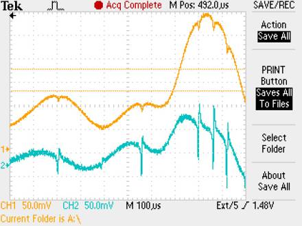
The figure above shows an oscilloscope trace of DC ERROR (blue) and ERROR IN (yellow) for the D2 87Rb F=2 <html>→</html> F'=2, 3 hyperfine crossover transition. Using the DC OFFSET, center the DC ERROR signal vertically about zero to insure that the lock point is at the center of the peak.
Adjust the laser current such that the center of the desired peak is exactly in the center of the oscilloscope. Switch LASER STATE from RAMP to LOCK. The ERROR IN signal should be held constant at the height of the desired peak and DC ERROR should be at zero volts with visible noise. If the ERROR IN value jumped when you clicked LOCK, then the laser jumped to the wrong transition or the servo is railed.
Adjust the COURSE and FINE GAIN knob to minimize the noise in the DC ERROR. Too high a gain usually kicks the laser out of lock or gives rise to sustained oscillations.
If the laser did not properly lock, try lowering the gain and attempting again. If you still cannot lock the laser, see the Laser Lock trouble-shooting section in Reconfigurable Laser Servo Manual.